DIY HP/Agilent 53131A 010 High Stability Timebase Option

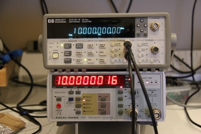
Having obtained a reasonably reliable 10MHz lab reference (see here) I decided to calibrate my Frequency Counter only to find that the stock oscillator provided in the HP 53151A is absolutely terrible – a joke even! I looked around for an “010 High Stability Timebase Option” but they are rare — and if you can find one not installed in a counter they are very expensive – in the few hundred dollars range at least — and buying one from HP is, well, expensive in the extreme. There are many second-hand 10MHz OCXO modules available, these are mostly stripped from old telecommunications, satellite or cellular equipment so they are plentiful and relatively cheap to buy too. I decided to make a clone 010 option board for my counter using a second-hand OCXO bought from e-bay. I designed a PCB to get a professional finish as well as a reliable upgrade for my counter. The main goal was to make an option board that just like the original could be automatically calibrated using the internal software and front panel controls so I had to use the same DAC chip (which is now obsolete) and basic topology of the original option board to make it work.

The result speaks for its self – with the OCXO running as the timebase, the counter is able to measure the 10MHz source it was calibrated with to a precision of 100th of one cycle with no error!

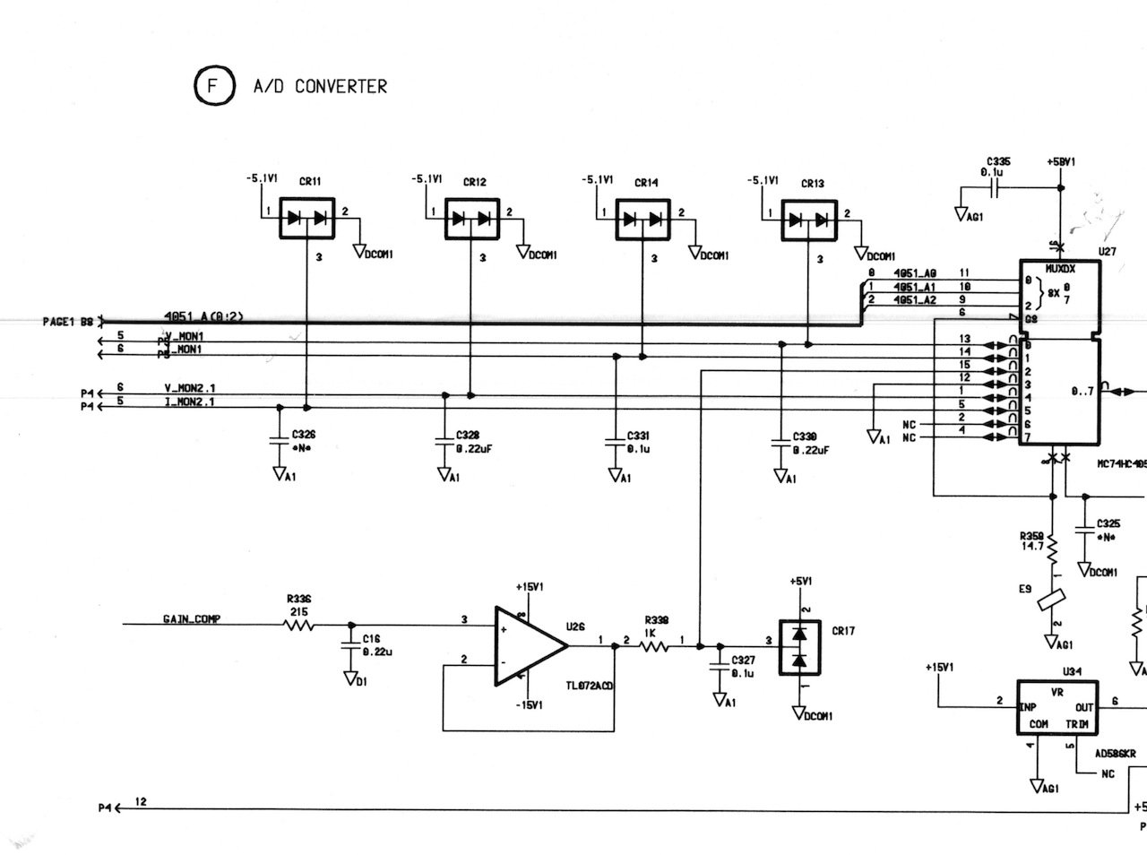
The schematic is pretty simple and self-explainatory. The counter seems to need a differential square wave clock drive, this is created using a high-speed differential output comparator part LM361. The DAC is an AD7243 part from Analog Devices, this part is now obsolete and not recommended for new designs but they are still available from various sources, albeit quite expensive parts. It would have been possible to design in a newer part but for the small number of units I wanted to make, it seemed a bit pointless to go to the effort as the recommended newer part actually requires different serial signaling, and this would have required some kind of serial protocol converter microcontroller. The DAC is driven by the counters microprocessor to calibrate and tune the timebase. The ADR4550 provides a high stability 5V reference for the ADC. The rest of the circuitry is basically power supply and signal filtering.

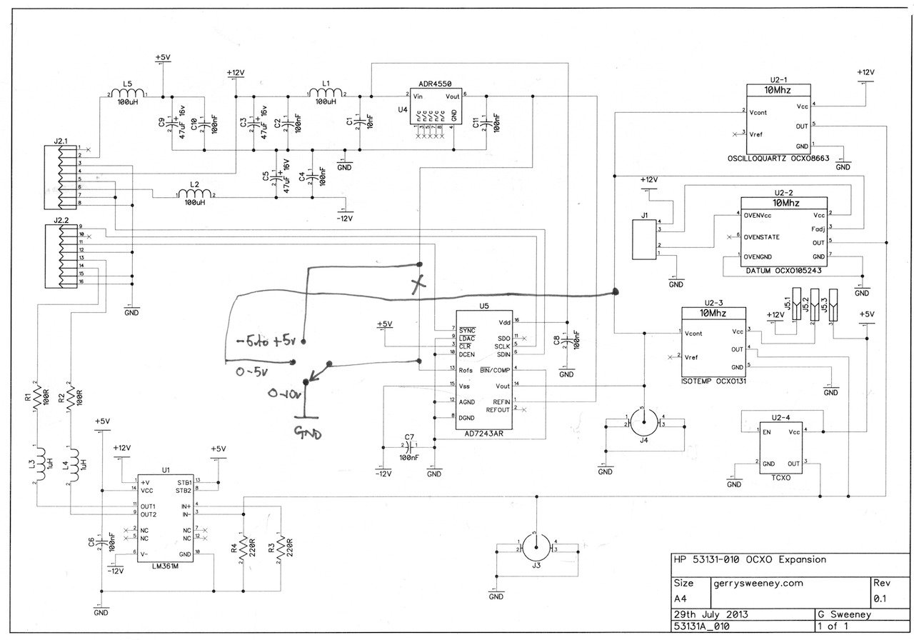
The PCB layout was designed to accommodate different OCXO footprints making it flexible. As well as supporting OCXO’s there are footprints for SMA connectors and you can even use a low-cost TCXO which cannot be automatically calibrated but is still a considerably better option than the oscillator built into the counter.

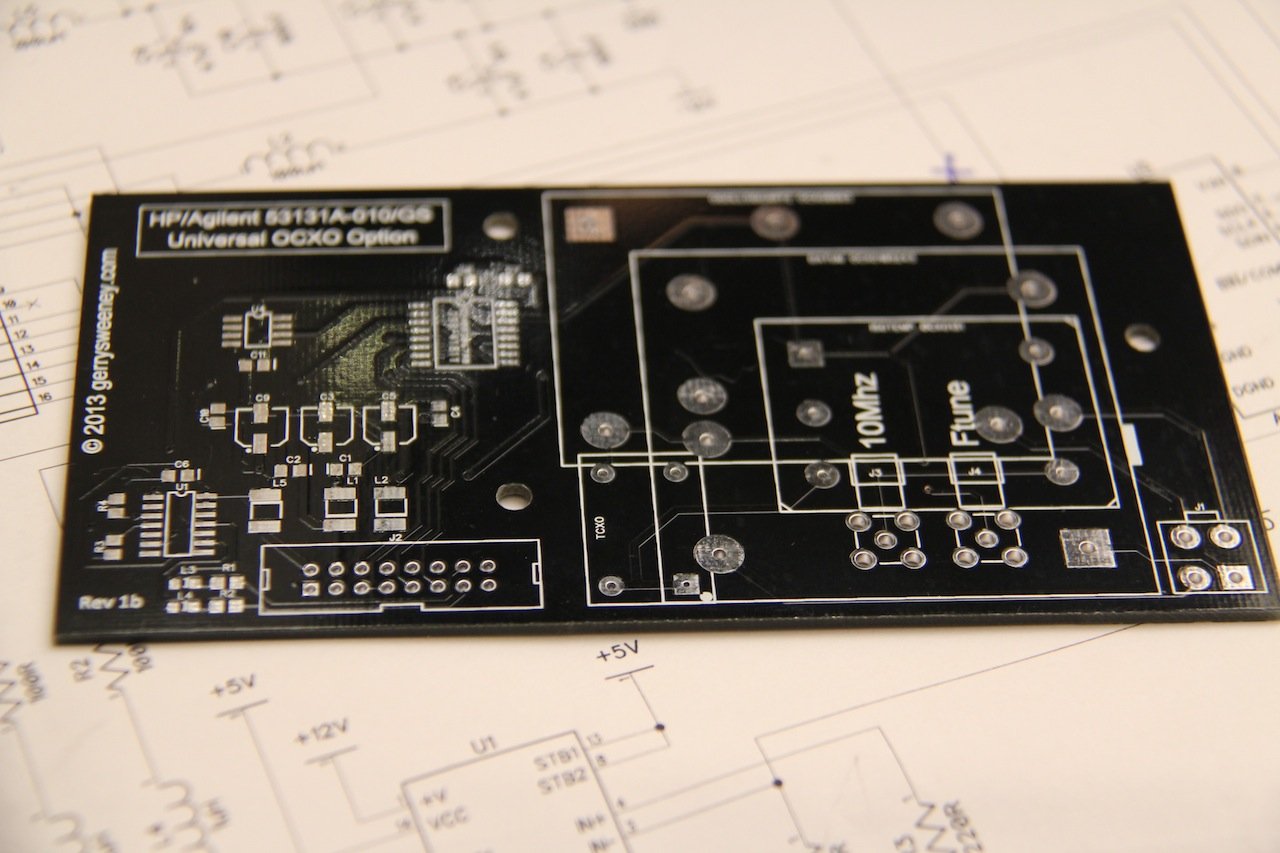
PCB’s Available : See here

The finished board fits really neatly inside the counter, and even fits around my previous Hard Power Switch Modification project.

Various Pictures

IMG_6028.JPG
IMG_6028.JPG
IMG_6026.JPG
IMG_6026.JPG
IMG_6031.JPG
IMG_6031.JPG
IMG_6034.JPG
IMG_6034.JPG
IMG_6024.JPG
IMG_6024.JPG
IMG_6038.JPG
IMG_6038.JPG

Catch you next time….

HP 53131A Hard Power Switch Modification

Following on from my previous post in relation to the HP 53131A Frequency Counter Teardown I have devised a reversible modification that replaces its soft power switch (where the switch mode PSU and the fan are running continuously when the unit is plugged into the wall outlet) to a hard power switch which properly turns the unit off from the front panel. The modification is simple to do, uses inexpensive parts and is completely invisible, it looks and feels like factory behaviour. It is will worth applying if you have one of these for bench use so you can leave it plugged into the wall without having the fan running and switch mode noise being generated when the unit is not in use. It’s hard to understand why HP did not include a hard power switch in the original design, you will see from my modification there is plenty of room, and it seems such an obvious thing to do. Anyway, I have created a video showing the details of the modification, if you have one of these frequency counters I hope you find the modification interesting and/or useful.

UPDATE: Having re-read the schematic again it appears that the unswitched +/-12v from the switch mode PSU are provided on the OCXO option connector J9. This would explain the design approach, the PSU will run the xtal oven even when switched off so when you are ready to use it, its instantly available. Thats fair enough except that many of these counters exist that do not have an OCXO option, and even with one fitted, I personally would be happy to know I have to switch it on in advance of using it.

NOTE: Please forgive the under-exposure on the first part of the video and the audio noise in a few places through it, I have a new camera setup and am getting used to it. The audio noise I believe comes from the phantom power not being liked by the wireless mic (I hope its that at least). The under-exposiure is just my misinterpretation of the zebra exposure indicator, you will see I get it right (or at least much better) in the second half of the video.

See you next time, and thanks for watching….

HP 53131A Frequency Counter Teardown and Spillage Clean-Up

One of the instruments I have is a HP 53131A Frequency Counter, and putting the positives of this unit aside, its by far the most annoying bit of test gear I have! Why? well for some reason, when you apply power to the thing the fan runs even when its switched off. This is because the power switch is a soft switch and with just the AC cord plugged in the fan runs and makes the annoying fan noise. This is a really poor design and certainly not one of HP’s shining examples of engineering….I like to be able to switch my stuff off without reaching around the back and having to pull the power chord or unplug from the wall outlet – just plain crappy! HP what where you thinking?

I thought I would tear it down and have a look and see why this is, and perhaps see if there is any possible modification I could come up with to improve on this. When I took it apart I found a real mess of dust and some kind of substance spillage so a full clean-up was needed which somewhat distracted me from the power switch problem.

While its in bits, I also do a quick run through of the major components of the circuit and have a quick look at the power supply and power switch circuits in some detail.

UPDATE: The clean-up also appears to have resolved the strange trigger problems I had seen previously with this counter. Well pleased…

Here is the Agilent 53131A Component Level Manual including schematics for the frequency counter

Thanks for watching…

My E3634A Mystery Explosion – WTF!

This is a short follow-up to a video where I was recently testing a Mayyuo M9711 DC Electronic Load (See Here) and I was using an Agilent E3634A Power Supply (which I previously fixed) as a power source. When I put the DC load into pulse mode within a few seconds the E3634A PSU exploded. What I heard was a loud pop, and a flash followed by a loud vibrating 50Hz hum, by which time I was able to reach the power switch and shut it down. I switched to another supply and continued with the test of the M9711 but today I thought I would open up (once agin) the E3634A and see what damage was done and what I found is a real mystery!

Did I imagine it all? Was there beer involved? Who knows, its a mystery!

Hope you enjoyed the video, catch you next time…

UPDATE – I found the smoke source

While tidying up I thought i would have a look at the two power MOSFET’s that failed and found the IRFP260 has a very small but visible smoke vent! I have added the photo’s below, I had to take these under the microscope x10 and x30 to see it. With the naked eye it looks like a light scratch.

HP/Agilent E3646A Power Supply Teardown & Repair

So I present the third in what is starting to feel like a long line of Agilent PSU repairs, but before you read on you should know that I have now depleted my collection of broken Agilent E36xx series power supplies so I will need to find another subject to blog about next time! That being said, even though I have blogged about two other PSU;s from the same family, I thought it would be worth videoing the repair exercise and at the same time try to demonstrate how I go about identifying and resolving a fault on this kind of circuit. The E3646A is a different model to the other two PSU’s I have repaired and blogged about – this one is a dual output 0-8v @ 5A / 0-20V @ 2.5A for each channel and the internals are different so I hope this will be of some use for anyone who may need to repair one of these.

Notes and Schematic Parts


You can download the Agilent E364xA Service Manual which include the schematics

I hope you find this useful or interesting. If you do please give the video a thumbs up and if you have any comments or suggestions please post them here and I will do my best to answer them.

Thanks for watching and catch you next time.

HP/Agilent E3634A Power Supply Teardown & Repair

Over a year ago now I repaired a HP/Agilent E3631A triple output PSU and have been using it very often ever since. Recently I bought an Agilent E3634A PSU which is a single output but high power supply, I bought it in non-working condition for not very much money (about $90). It turned out to be a non-trivial task, with physically burned out components and a difficult to track down and understand secondary problem. The components to repair the supply cost less that $20 and the repair exercise was challenging and educational so well worth the effort.

SMOKIN’ HOT…..

I decided that for this repair I would try doing a video teardown and repair which I have not done before. The repair took quite a few hours in the end, although I carried out the repair over about 4 weeks elapsed.

This is a really useful addition to my work bench, the high power nature of this supply makes it very useful for working in low voltage systems like audio amplifiers communications equipment and automotive applications that have high power requirements.

The Agilent E3634A Service Manual with schematics is available on the internet for download, I have provided a link here for convenience.

See you next time…