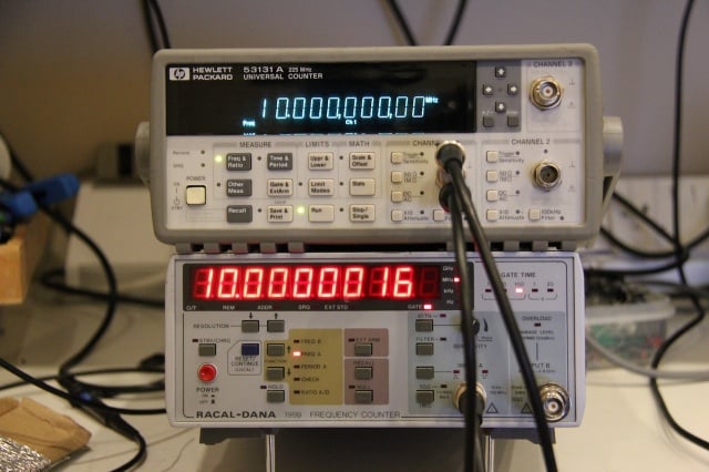
I have been using this Racal-Dana 1999 counter for a long time and in the last few months it started to suffer from an intermittent fault where it would appear to freeze and stop responding. Banging the unit on the side with the palm of my hand would get it going again, and when doing this it would often restart as if its been powered on. In addition to this fault, the counter suffers from an altogether common problem with the buttons on the front which loose any tactile feel to them and become difficult to actuate – this is a common problem on these counters and thats down to the poorly designed switches Racal used for its frequency counter range.
I identify the fault and fix the problem and I replace all the buttons with ones that work and end up with a fully restored frequency counter once again.
I have made the manual including schematics available in the attachments section of this article for your convenience
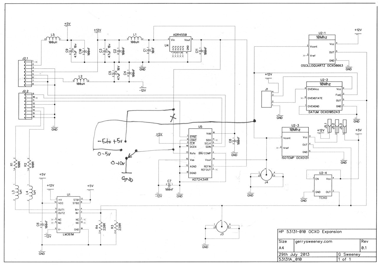
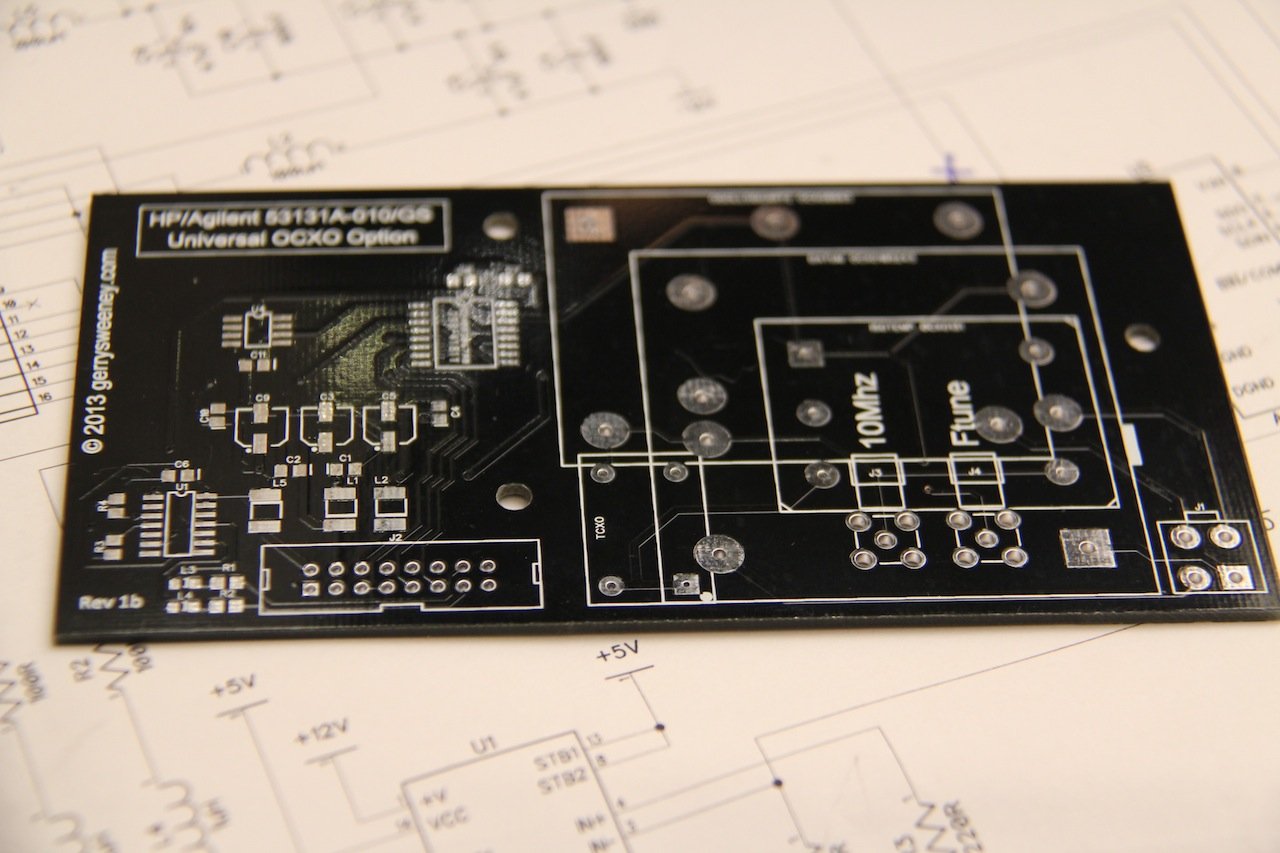
Having obtained a reasonably reliable 10MHz lab reference (see here) I decided to calibrate my Frequency Counter only to find that the stock oscillator provided in the HP 53151A is absolutely terrible – a joke even! I looked around for an “010 High Stability Timebase Option” but they are rare — and if you can find one not installed in a counter they are very expensive – in the few hundred dollars range at least — and buying one from HP is, well, expensive in the extreme. There are many second-hand 10MHz OCXO modules available, these are mostly stripped from old telecommunications, satellite or cellular equipment so they are plentiful and relatively cheap to buy too. I decided to make a clone 010 option board for my counter using a second-hand OCXO bought from e-bay. I designed a PCB to get a professional finish as well as a reliable upgrade for my counter. The main goal was to make an option board that just like the original could be automatically calibrated using the internal software and front panel controls so I had to use the same DAC chip (which is now obsolete) and basic topology of the original option board to make it work.
The result speaks for its self – with the OCXO running as the timebase, the counter is able to measure the 10MHz source it was calibrated with to a precision of 100th of one cycle with no error!
The schematic is pretty simple and self-explainatory. The counter seems to need a differential square wave clock drive, this is created using a high-speed differential output comparator part LM361. The DAC is an AD7243 part from Analog Devices, this part is now obsolete and not recommended for new designs but they are still available from various sources, albeit quite expensive parts. It would have been possible to design in a newer part but for the small number of units I wanted to make, it seemed a bit pointless to go to the effort as the recommended newer part actually requires different serial signaling, and this would have required some kind of serial protocol converter microcontroller. The DAC is driven by the counters microprocessor to calibrate and tune the timebase. The ADR4550 provides a high stability 5V reference for the ADC. The rest of the circuitry is basically power supply and signal filtering.
The PCB layout was designed to accommodate different OCXO footprints making it flexible. As well as supporting OCXO’s there are footprints for SMA connectors and you can even use a low-cost TCXO which cannot be automatically calibrated but is still a considerably better option than the oscillator built into the counter.
As a follow-up to a previous blog post where I created a seven decade programmable resistor substation for use during electronic circuit prototyping and development, I thought I would expand on the concept and develop a decade capacitor solution to complement the decade resistor board. This new board is a five decade programmable capacitance and is in exactly the same form factor as the previous resistor project. The capacitance can be programmed in the range of 100pF through 9.9999uF in 1000pF increments. The tolerance of the capacitance is five (5%) percent.
My goal was to keep costs down while making the board usable and functional and reliable so I continued to use the 0.1″ jumpers I had used for the resistor board. However, to achieve a programmable capacitance you need to use small capacitors and parallel them to obtain the desired value, and the challenge here was how to achieve that with jumpers. In the end I took the simple approach and provided 10 jumpers for each decade, but instead of a two-pin header row I used a three pin header row so each of the 10 jumpers has an “on” (1) or “off” (0) position. I concede that the board is slightly more difficult to use than the resistor board, and thats simply because of the number of jumpers – dialling in a value involves moving multiple jumpers per decade. However, with the cost to use high quality switches I felt that the infrequent nature of use for the board, it was a reasonable compromise both in terms of design theme consistency and cost.
When working on linear circuits, in particular around op amps, PSU’s and other circuitry that needs response tuning, having a decade capacitance to hand when prototyping is a very valuable tool – not for day to day use of course, but when you are doing that specific job that needs this, its worth its weight in gold.
If you are interested in one of these boards I have had a bunch of them made and am selling them. You can buy them on http://tindie.com or if you prefer on e-bay – simply search for “gerrysweeney” on either system to find the items.
This is a follow-up to my previous article here. When testing the 1 PPS output I found some strange output which needed further investigation. I also decided to make further use of the microcontroller and status LED to indicate the 1 PPS signal to provide a degree of visual confidence that the frequency standard was working.
The 1 PPS Channel
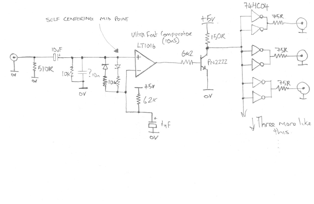
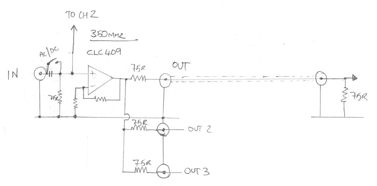
Here is the outline schematic of the digital channel of the video amp that is now used for the 1 PPS signal.
The fast comparator used in this circuit is an LT1016
The Micro-controller
When I first tried to implement this I used (or tried to use) the edge trigger interrupt capability which on the face of it should have been the perfect solution. However, no matter what I tried I could not get it to work, the best I managed to achieve was getting it to work some of the time, but it was very random. I suspect this was down to the way in which the PIC12X handles interrupts and context state saving implemented by the compiler, I read somewhere on the microchip forums that this issue *could* be resolved by upgrading to the PRO version of the compiler…..hmmmmmmm. Anyway, I decided to change tact and poll for the 1PPS signal which meant I also had to construct a really simple pulse stretcher circuit to ensure I was able to catch each pulse. Not as elegant as an interrupt-driven solution but it works. I think the more advanced PIC18Fxxx series micro controllers would have worked using interrupts but those are big chips and I was already committed to the PIC12F675.
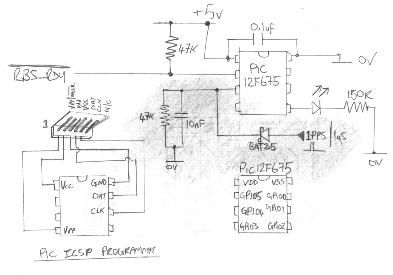
Here is the schematic for the micro controller which now also monitors the 1 PPS output of the RBS. The shaded area is what has been added to the circuit since the previous article.
Here is the firmware source code with the 1PPS implementation added. Its implemented as a simple state machine in run mode, I have tried to keep the code simple to read.
And for those of you that just want to program the chip, here is the compiled HEX file.
Having gotten myself a Rubidium Frequency Standard I found that the unit on its own is not that useful, its really just a component and needs really a supporting PSU and a decent enclosure to make it useful. I was searching around for something suitable when I was directed to a robust quality unit being sold on e-bay for just £20 with an unbelievable level of re-usable content and turned out to be an almost perfect solution to making the Rubidium Standard a useful Lab item. Rarely does such a fine marriage of junk bits come together to make something really useful?
I had a lot to cover, the whole thing was built in an afternoon and as a result, this is a long video at 1 hour 16 mins so be prepared…
Video of the project build. 1hr 16mi
The PIC Micro-controller – PIC12F675 The original plan was to use the PIC for three functions, the first was to make the power LED flash while the RFS was warming up and on solid when locked. The second was to generate a 1 PPS signal from the 10Mhz signal and the third was to generate a PWM signal to control the fan speed. As it turns out the RFS already has a 1 PPS output on Pin 6 of the DB9 connector so there was no need for this. It also transpired that the only fan I had to hand was a three wire fixed speed fan, so I also did not need the PWM signal, this left me with just the power LED to deal with which is what the PIC ended up controlling. Here is the schematic for the PIC and the source code.
And the compiled HEX file if you want to just program the chip without compiling
The Video Amp – Extron ADA 6 300MX HV The video amp unit I used in this hack is made by Extron and the model number (on the front panel) is ADA 6 300MX HV. When I communicated with the seller, he said he had about 30 of them, so if this is useful to you and you want to make your own I would go grab yourself one before they are gone. The basic outline schematic for an input channel is here:
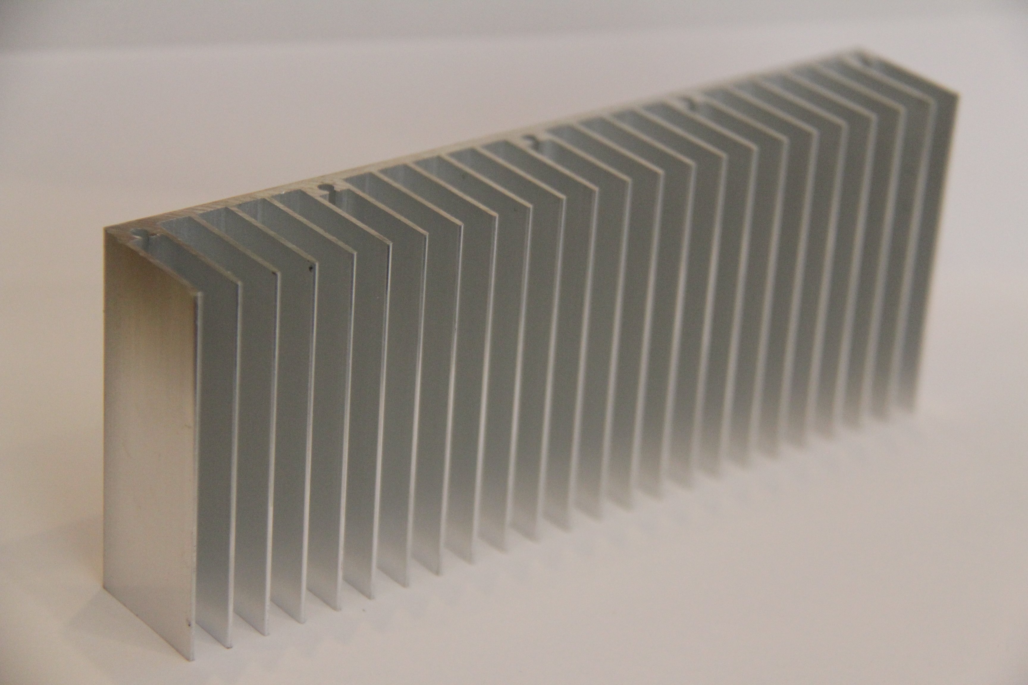
The heat sink I have ordered can be found on e-bay, search for “150x25x60mm Aluminum Heat Sink for LED”.
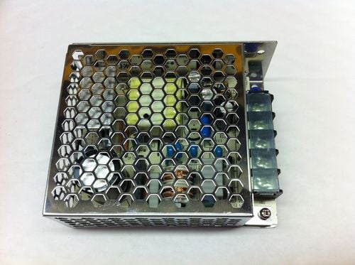
The switch mode PSU I used can also be found on e-bay, search for “Enclosed Power Supply SMPS,15V,2.4A,36W, it is made by TDK-Lambda and the part number is LS35-15”
As part of the process of upgrading my counter to have a DIY high stability OCXO (Oven Controlled Crystal Oscillator), someone who watched my videos had designed a DIY 3GHz Channel 3 53131A-030 option board. The original from Agilent is very expensive (obviously) and there are clones you can get on e-bay which are a quarter of the price Agilent charge which is why he decided to design his own. His name is Andy and when he saw my video’s he got in touch and offered me one of the PCB’s to which I of course said YES PLEASE 🙂
Now as it turned out, when Andy constructed his own board he had enough components left over so also constructed and tested one for me which was a really kind thing to do and very unexpected too. In exchange for this I have insisted that I can build him an OCXO board while I am doing mine to return the favour.
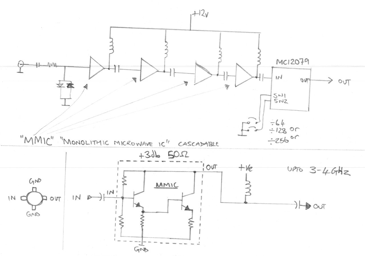
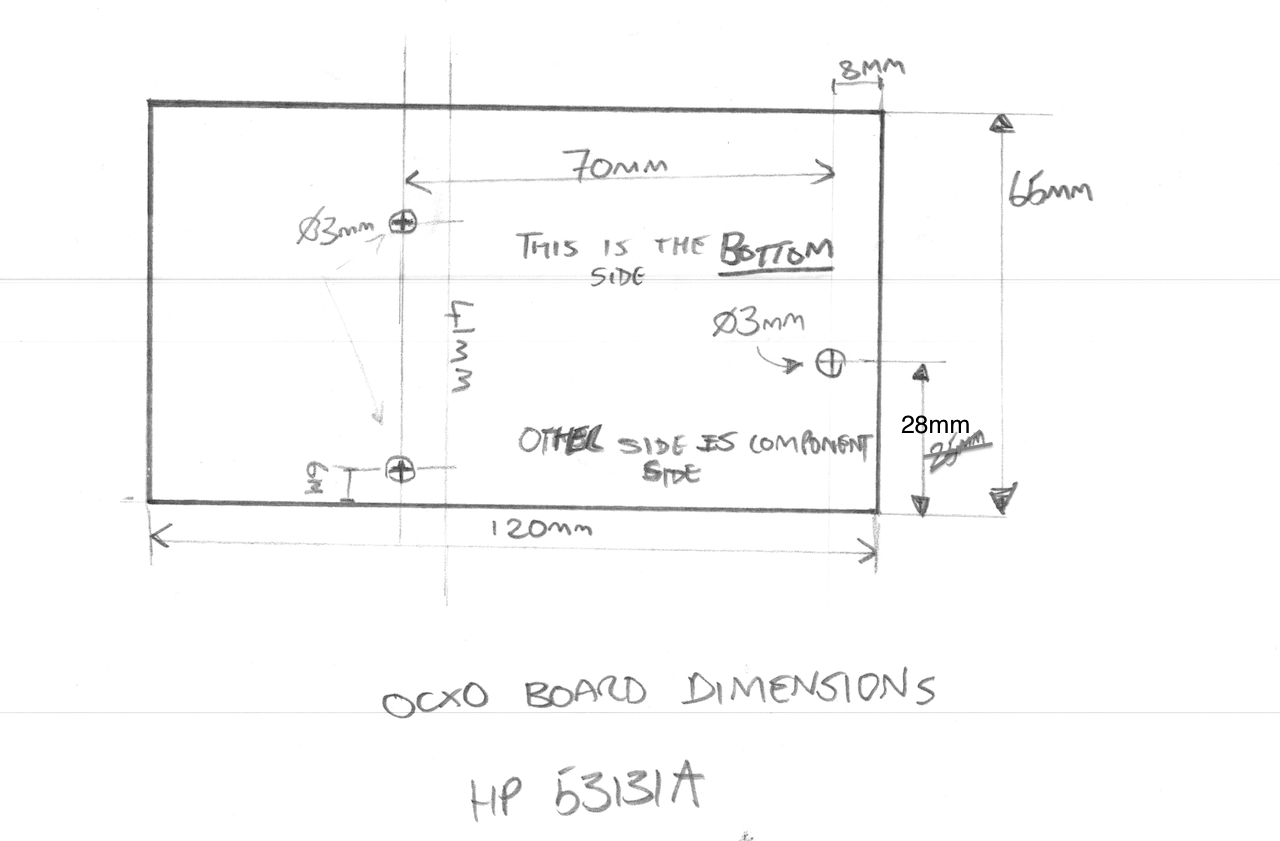
Anyways, I thought I would do a video to show the HP/Agilent 53131A-030 DIY 3GHz Cannel 3 Option board getting fitted to my counter. I also spend some time explaining how the pre-scaller circuit works and in basic terms what MMIC’s are and how they work too. I also make an adaption to my previous hard power switch modification to make way for the upcoming DIY OCXO board, and I measure up to get the exact board dimensions and mounting hole positions I need for the OCXO PCB layout.
The entire work and full attribution for the DIY 030 option board/PCB goes to Andy, so Andy – thank you so much for making one of these for me – I really appreciate it.
PLEASE NOTE: I will not put Andy’s Youtube/EEVblog ID here unless he asks me to, and I will not pass on his details without his express permission so please don’t ask – I respect people’s privacy. If Andy does want to share his details in connection with this project then I will gladly put them here.
PLEASE ALSO NOTE: The schematic drawing below is technically incomplete and is meant as an illustrative block diagram. In the real circuit there is also a resistor in series with each inductor at the top of each MMIC to set up the right DC conditions.