This is a follow-up to my previous article here. When testing the 1 PPS output I found some strange output which needed further investigation. I also decided to make further use of the microcontroller and status LED to indicate the 1 PPS signal to provide a degree of visual confidence that the frequency standard was working.
Various Pictures
Photo Album 9
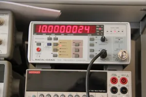
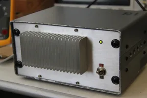
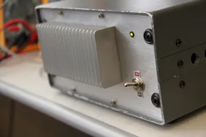
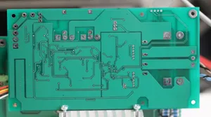
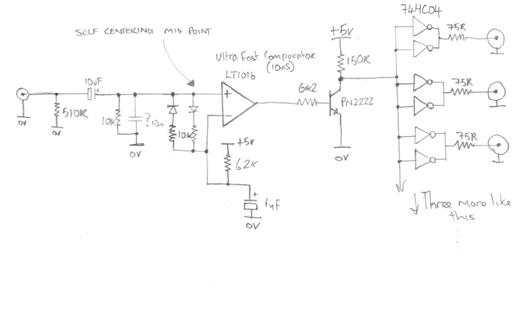
The 1 PPS Channel Here is the outline schematic of the digital channel of the video amp that is now used for the 1 PPS signal. 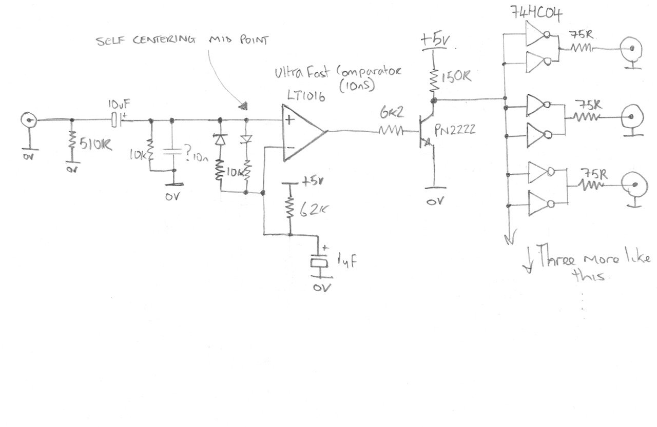
The fast comparator used in this circuit is an LT1016
The Micro-controller When I first tried to implement this I used (or tried to use) the edge trigger interrupt capability which on the face of it should have been the perfect solution. However, no matter what I tried I could not get it to work, the best I managed to achieve was getting it to work some of the time, but it was very random. I suspect this was down to the way in which the PIC12X handles interrupts and context state saving implemented by the compiler, I read somewhere on the microchip forums that this issue *could* be resolved by upgrading to the PRO version of the compiler…hmmmmmmm. Anyway, I decided to change tact and poll for the 1PPS signal which meant I also had to construct a really simple pulse stretcher circuit to ensure I was able to catch each pulse. Not as elegant as an interrupt-driven solution but it works. I think the more advanced PIC18Fxxx series micro controllers would have worked using interrupts but those are big chips and I was already committed to the PIC12F675.
Here is the schematic for the micro controller which now also monitors the 1 PPS output of the RBS. The shaded area is what has been added to the circuit since the previous article. 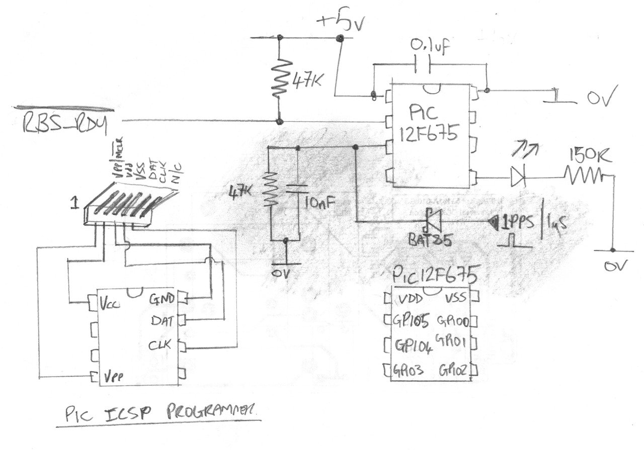
Here is the firmware source code with the 1PPS implementation added. Its implemented as a simple state machine in run mode, I have tried to keep the code simple to read.
#include <xc.h>
// PIC12F675 Configuration Bit Settings// CONFIG #pragma config FOSC = INTRCIO // Oscillator Selection bits (Internal oscillator: GPIO on GP4/GP5) #pragma config WDTE = OFF // Watchdog Timer Enable bit (WDT disabled) #pragma config PWRTE = OFF // Power-Up Timer Enable bit (PWRT disabled) #pragma config MCLRE = OFF // GP3/MCLR pin function select (GP3/MCLR pin function is digital I/O, MCLR internally tied to VDD) #pragma config BOREN = OFF // Brown-out Detect Enable bit (BOD disabled) #pragma config CP = OFF // Code Protection bit (Program Memory code protection is disabled) #pragma config CPD = OFF // Data Code Protection bit (Data memory code protection is disabled)// IMPLEMENTATION STRATEGY // // PIN ASSIGNMENTS // 2 = RFS\_RDY signal from Pin 6 (GPIO5) // 4 - 1PPS signal // 5 - Front Panel LED //// We are running the chip at 4Mhz #define XTAL\_FREQ 4000000
#define CLK_1PPS GPIObits.GPIO4#define LED_STATUS GPIObits.GPIO2#define RFS_READY GPIObits.GPIO5
void main(void){  // Used as LED state machine control variable  char _led_state = 0;
  ADCON0bits.ADON = 0; // Turn off the ADC  ANSELbits.ANS = 0; // Make all inputs digital  VRCON = 0;    // Turn off the internal voltage reference  CMCON = 0x7;  // Turn off the comparator
  // Set up our I/O pins  TRISIObits.TRISIO2 = 0;     // Make GPIO2 an output - LED  TRISIObits.TRISIO4 = 1; // Make GPIO4 an input - 1PPS counter input  TRISIObits.TRISIO5 = 1; // Make GPIO5 an input - RFS\_READY
  while(1)  {    if(RFS_READY == 0)    {      // This is when we are in run mode.      // We are polling the 1 PPS signal, if we sense a "1" we set the      // _led_state variable to the number of 10ms periods you want. In      // this case I want about 80ms. Once this is set the state machine      // below will hold the LED on and wait 10ms until ir reaches 2,      // and then normal state resumes, the end result being an LED thats      // lit normally, and pulses brightly for about 80ms on each 1pps      // count.      if(CLK_1PPS == 1)        _led_state = 10;
      // This is a simple state machine that will run the LED      // at one third power by outputting a 33% duty cycle square      // wave. Each time around the loop the state variable will      // count 0-1-2-0-1-2...etc LED on for 0, and off 1 & 2.      // When the 1PPS interrypt is fired, the state machine      // holds the LED on at full brightness (100% duty)      switch(_led_state)      {        case 0:          LED_STATUS = 1;          _led_state = 1;          break;        case 1:          LED_STATUS = 0;          _led_state = 2;          break;
        case 2:          LED_STATUS = 0;          _led_state = 0;          break;
        default:          _led_state--;          LED_STATUS = 1;          _delay(10000);          break;        }      }      else      {        // If we get in here we are in warm-up mode. We blink the        // LED with a short on period (20%) and a long off period (80%)        // about three blinks a second.        if(LED_STATUS == 0)        {          LED_STATUS = 1;          _delay(75000);        }        else        {          LED_STATUS = 0;          _delay(300000);        }      }    }  }
And for those of you that might want to just program the chip, here is the compiled HEX file.
:08000000FD2BB92BBD2BC32B16:100746008312A3011F10F03083169F05990107300D:10075600831299008316051105168516EA2B051EC8:10076600D32B0A30A0002008A300D32B0515A30124:10077600A30AEA2B05110230A0002008A300EA2BE9:100786000511A301EA2B0130A30205150D30A100C6:10079600FB30A000A00BCD2BA10BCD2BD22BEA2B2F:1007A600831223088400033004020318C62B00308A:1007B6008A00013004078200EA2B05156230A10089:1007C6006530A000A00BE52BA10BE52BEA2B8312CD:1007D600851EB22B051DE02B05110230A2008630C6:1007E600A1009930A000A00BF62BA10BF62BA20BB3:0807F600F62BEA2B8301A32B73:02400E009431EB:00000001FFCatch you next time…
Loading comments…