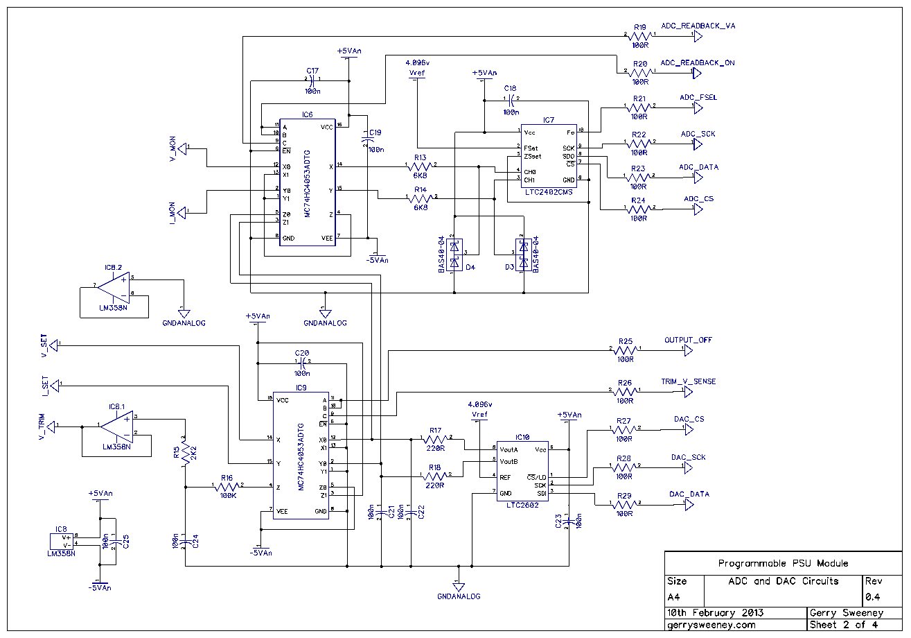
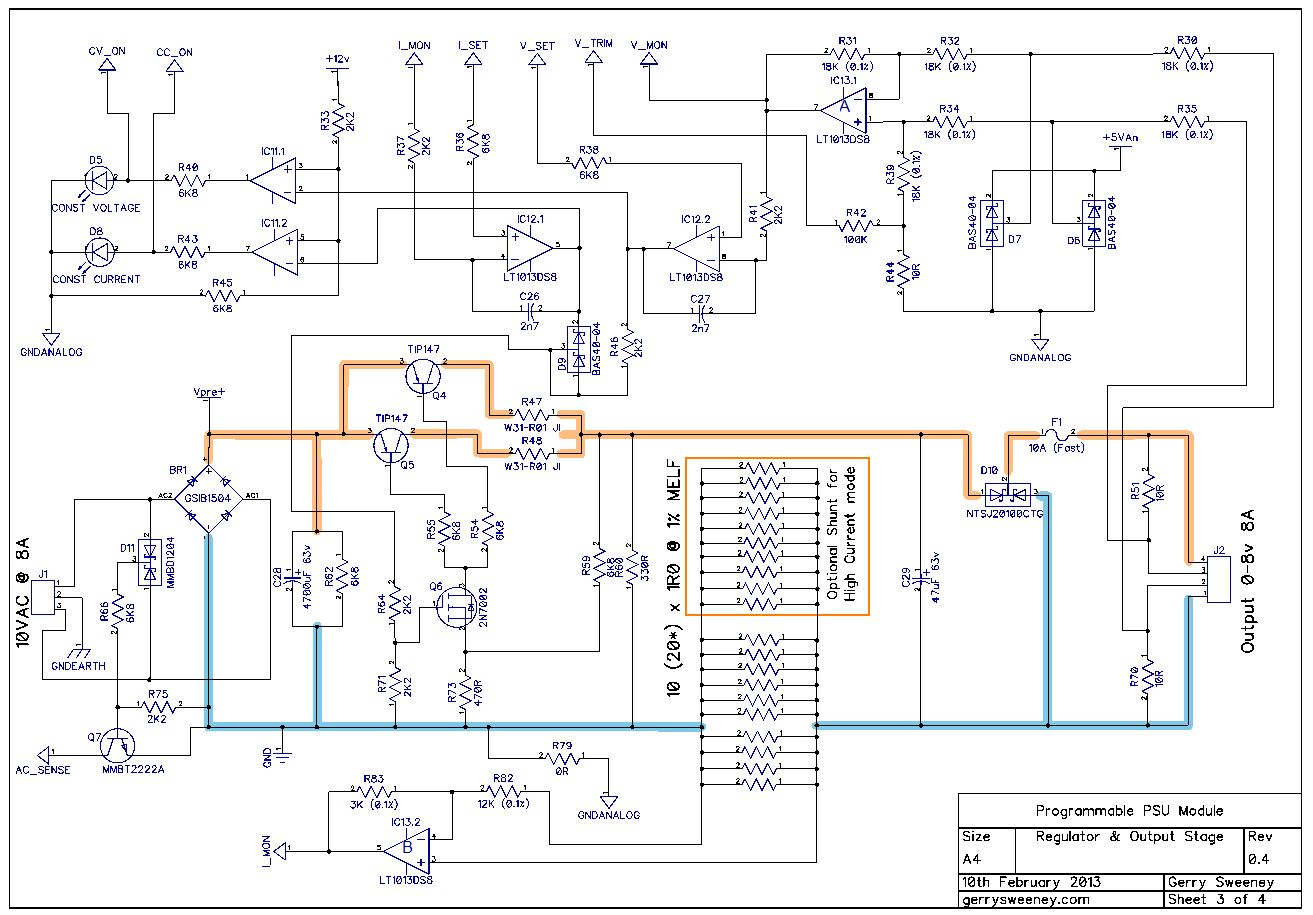
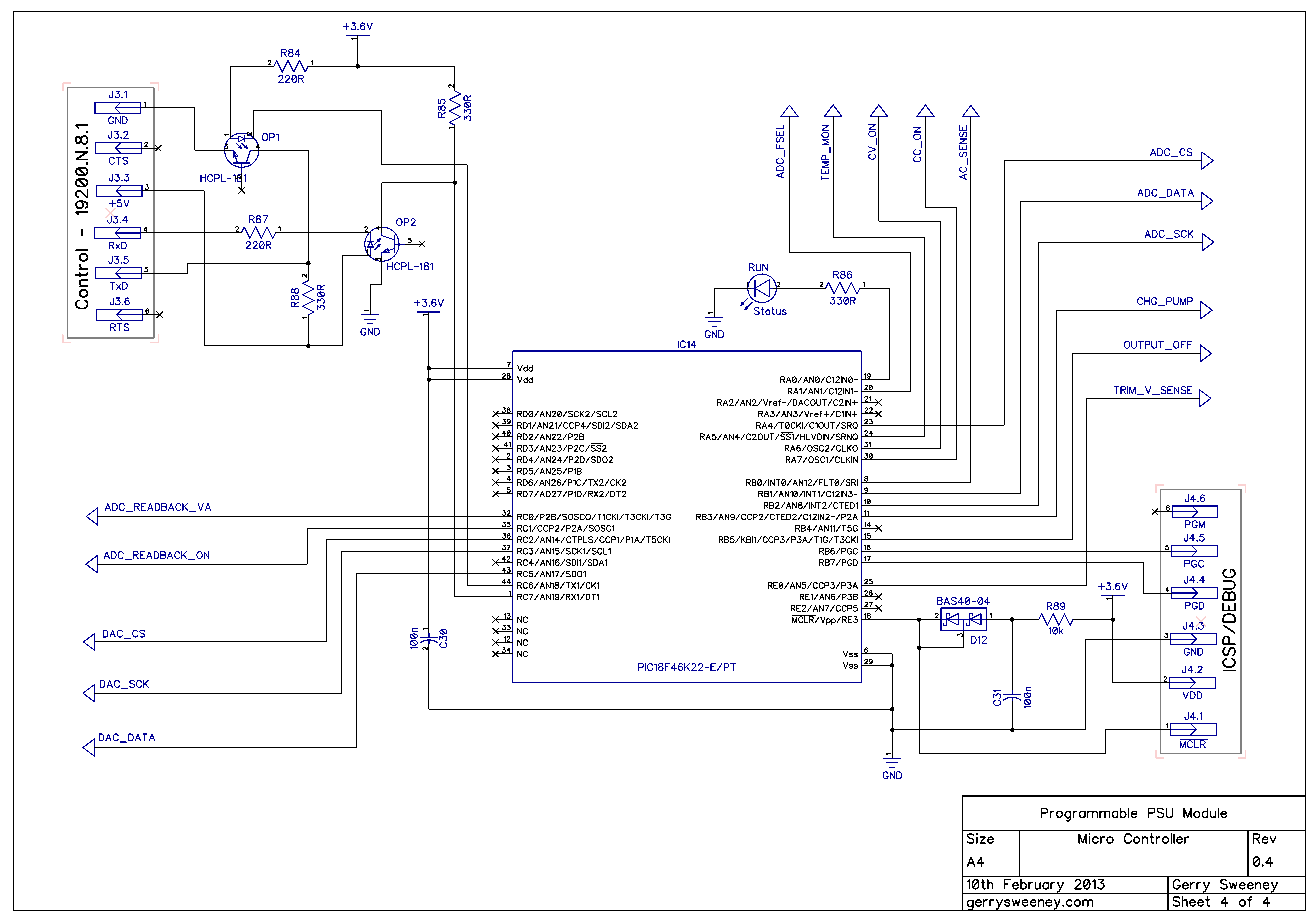
Here is the latest Revison 0.4 schematic which represents the power supply design as described in this blog and videos with the latest round of prototyping and testing.
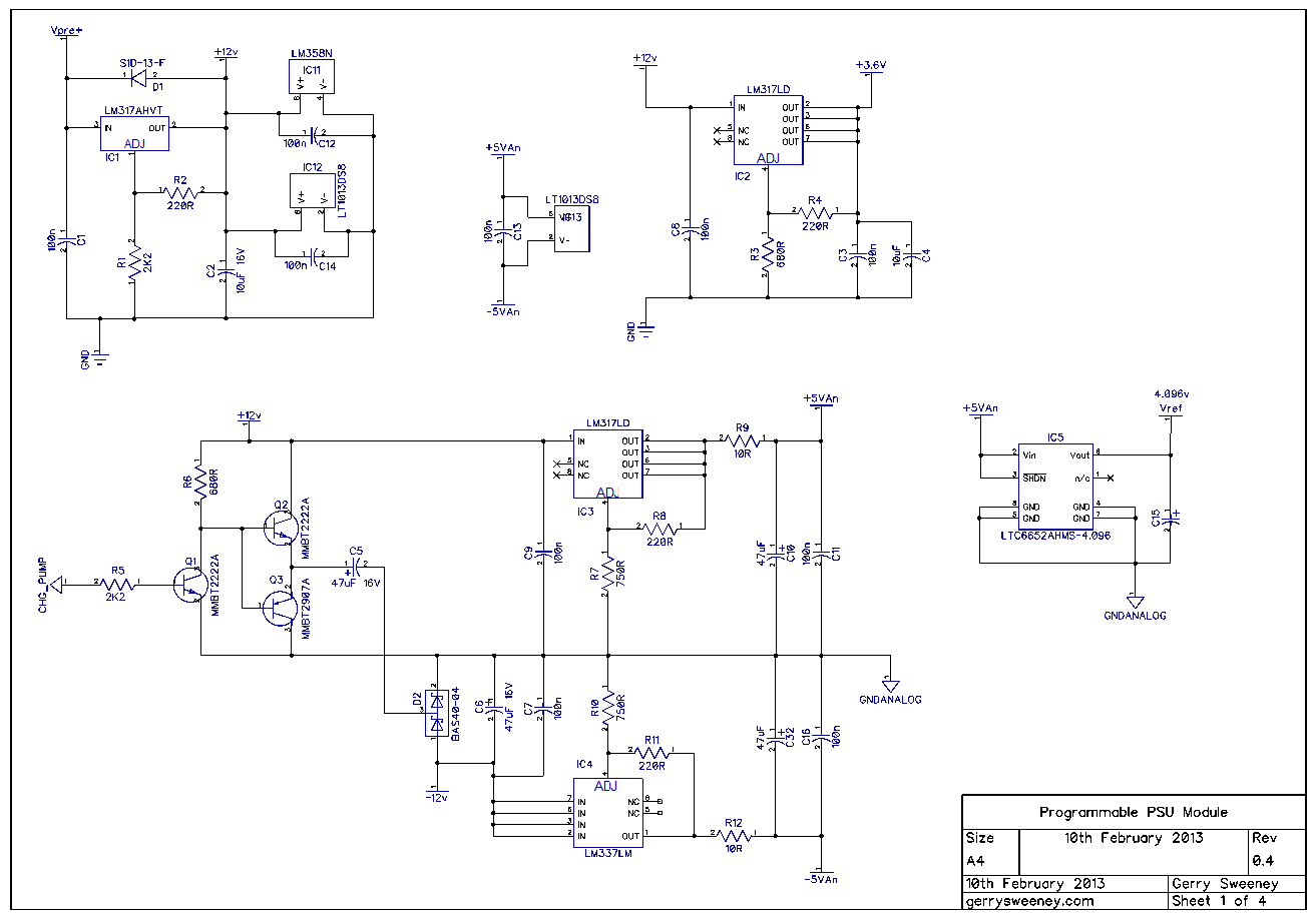
The headline changes from last time are as follows: –
- I have added -Ve supply using a simple charge pump and a PWM drive from the micro controller.
- I have added a difference amplifier to correctly handle remote voltage sensing for both PSU voltage control and output voltage read back
- I have modified the design to use low-side current sensing instead of high-side current sensing. In doing so I have dropped the use of the high side current sense amp MAX4080 and made use of a spare op amp element instead. This saves a $3 part and replaces it with half of a $2 part
- Removed dedicated buffer amp previously added to drive the ADC, the new design removes the need for this because the voltage and current monitoring are better buffered now. This saves another $2 part.
- Moved to a faster micro controller PIC18F46K22 which has more memory, more PWM outputs and more I/O pins. No real reason apart from I needed a second PWM output. The firmware is pretty much compatible.
Here is a video overview of the design changes and latest prototype hardware and test setup as well as some basic tests showing load regulation and programmable voltage accuracy benchmarked against a calibrated HP 34401A bench meter.
NOTE: I used a different mic setup and the sound is really poppy and crappy! My apologies…..My dustbin now has a new microphone in it!
You can download the hand-drawn illustrations used in the video here: PSU Part 11 Illustrations
So I am working on the final PCB now, in Part 12 I should have a finished module….whoop whoop….Please do comment and like the videos if you find them interesting. Thank you for watching.