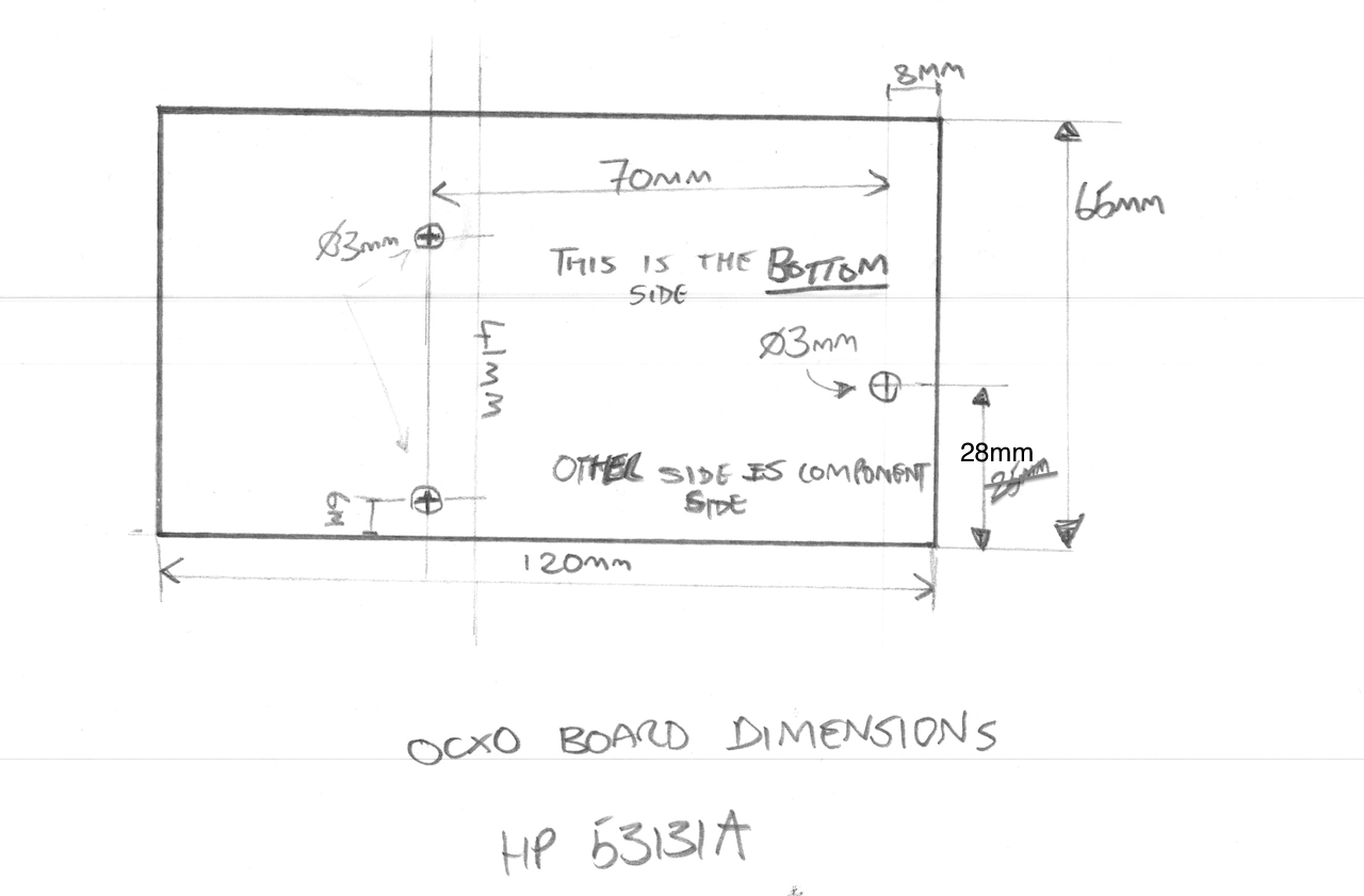
Following on from the project to build a DIY OCXO upgrade option for my HP/Agilent 53131A Frequency Counter I had a large number of requests for me to make the PCB’s available so others can built there own. I now have some PCB’s and are making them available for sale. I will also be making some fully assembled and tested/verified boards including an OCXO, ready-made cable and mounting stand-off’s, there will only be a limited number of these so if you are interested, let me know, first come first serve and when they are gone they are gone.
Now, someone made a comment on hackaday stating that the reason why these OCXO’s are on e-bay is because they are no good. Well I can understand why one could draw that conclusion but having now played with in access of 50 of these OCXO’s I can tell you that they all pretty much violently agree with each other and they also agree with the Rubidium Frequency Standard I have, so given they are from different sources and all free-running I am pretty comfortable they are good and usable quality devices. I read a lot on the net about “burn in time” and the general consensus seems to be, the longer you age and heat a crystal oscillator the more stable (in terms of drift) it becomes. Now I don’t know how true that is, but if it is true, then by definition, using recovered OCXO’s must actually be a good thing. Of course if you feel the need to pay a couple of hundred dollars for a new OCXO then you can of course do that – but I am pretty sure that it does NOT guarantee you any better performance, it just buys you the right to get compensated if you happen to find it does not meet the performance specifications quoted by the manufacturer and it might make you feel a little more confident. Anyway I guess the results speak for themselves and for a home lab these OCXO’s are more than good enough I think.
Here is a short video showing the various configurations built and working as well as a quick overview of the PCB its self and the configuration options.
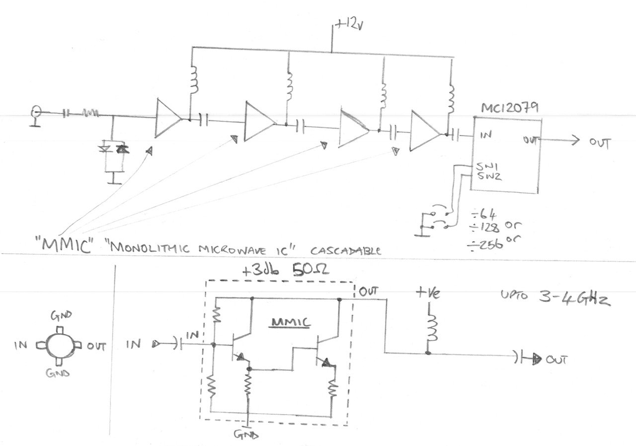
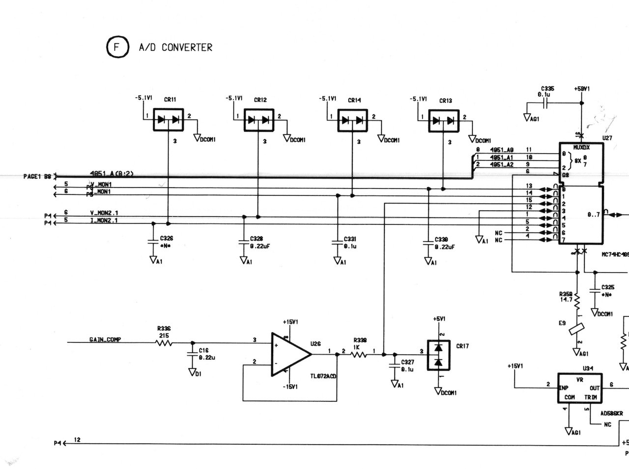
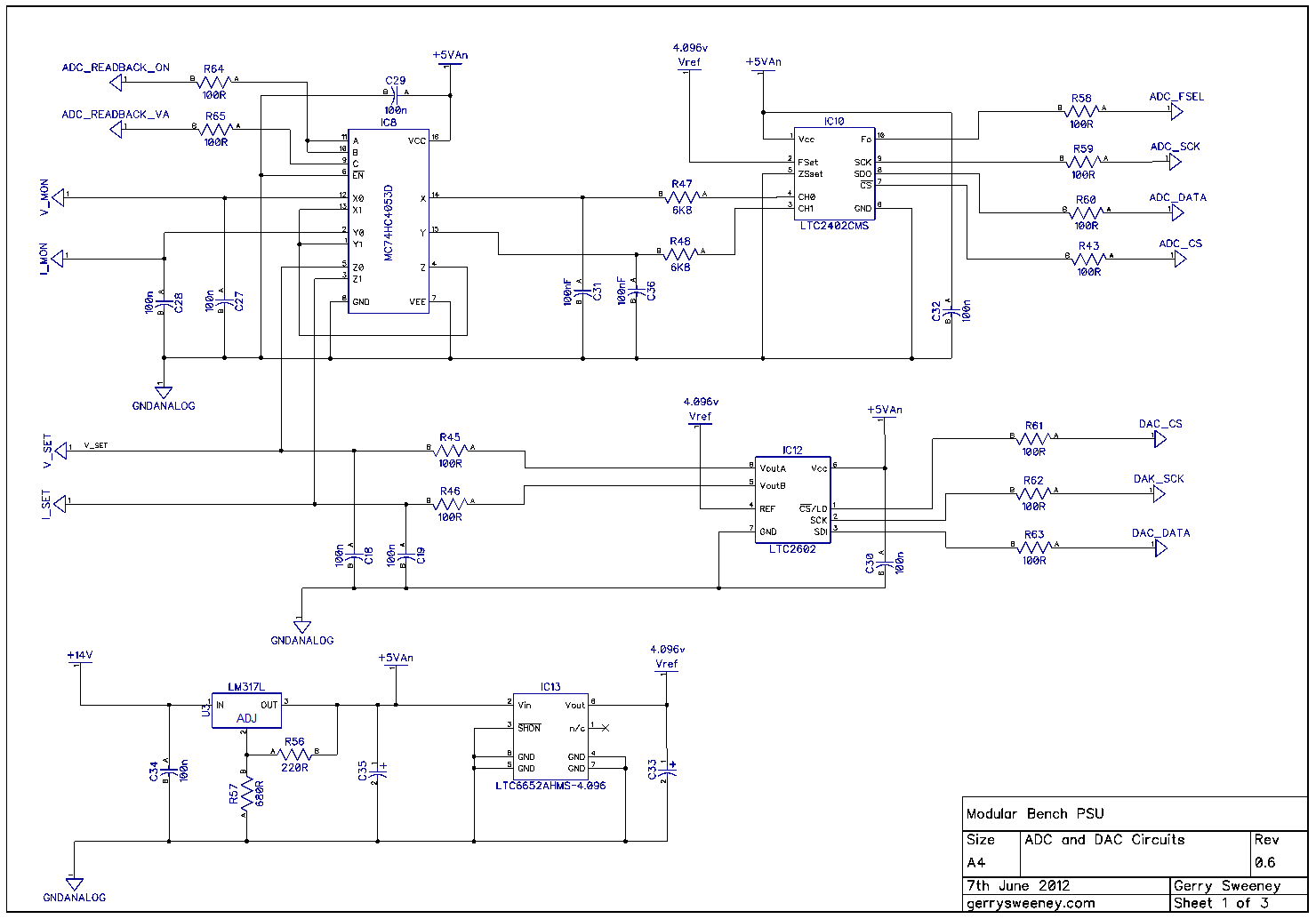
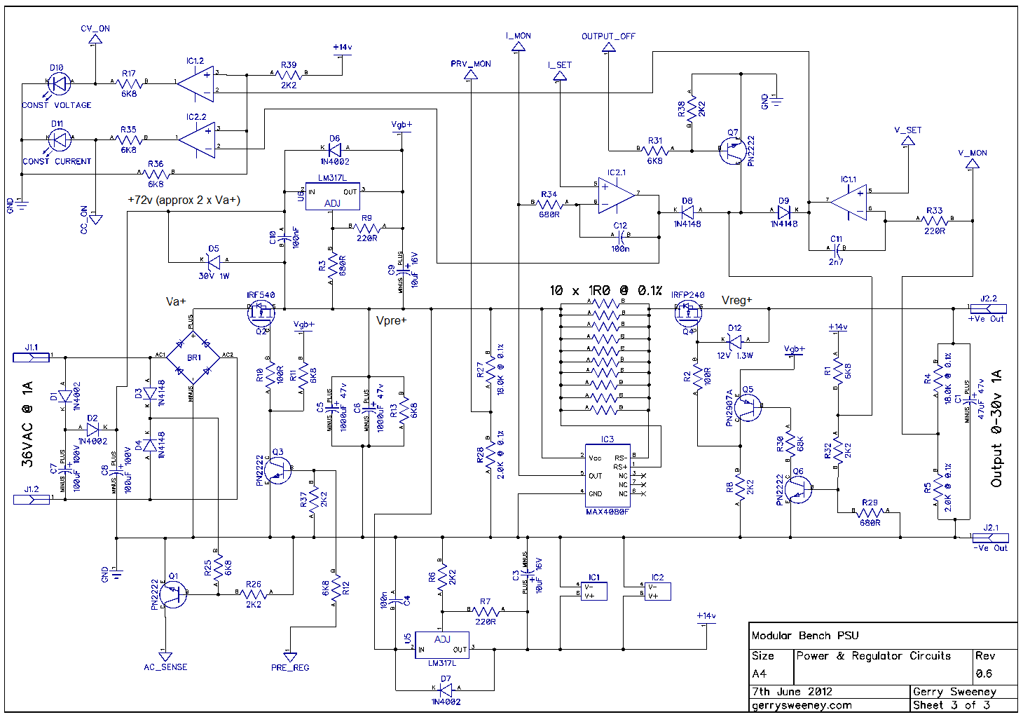
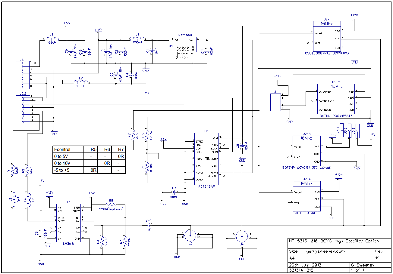
The Schematic
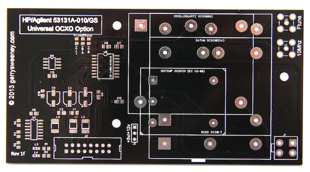
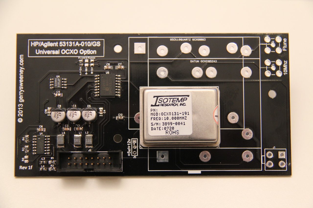
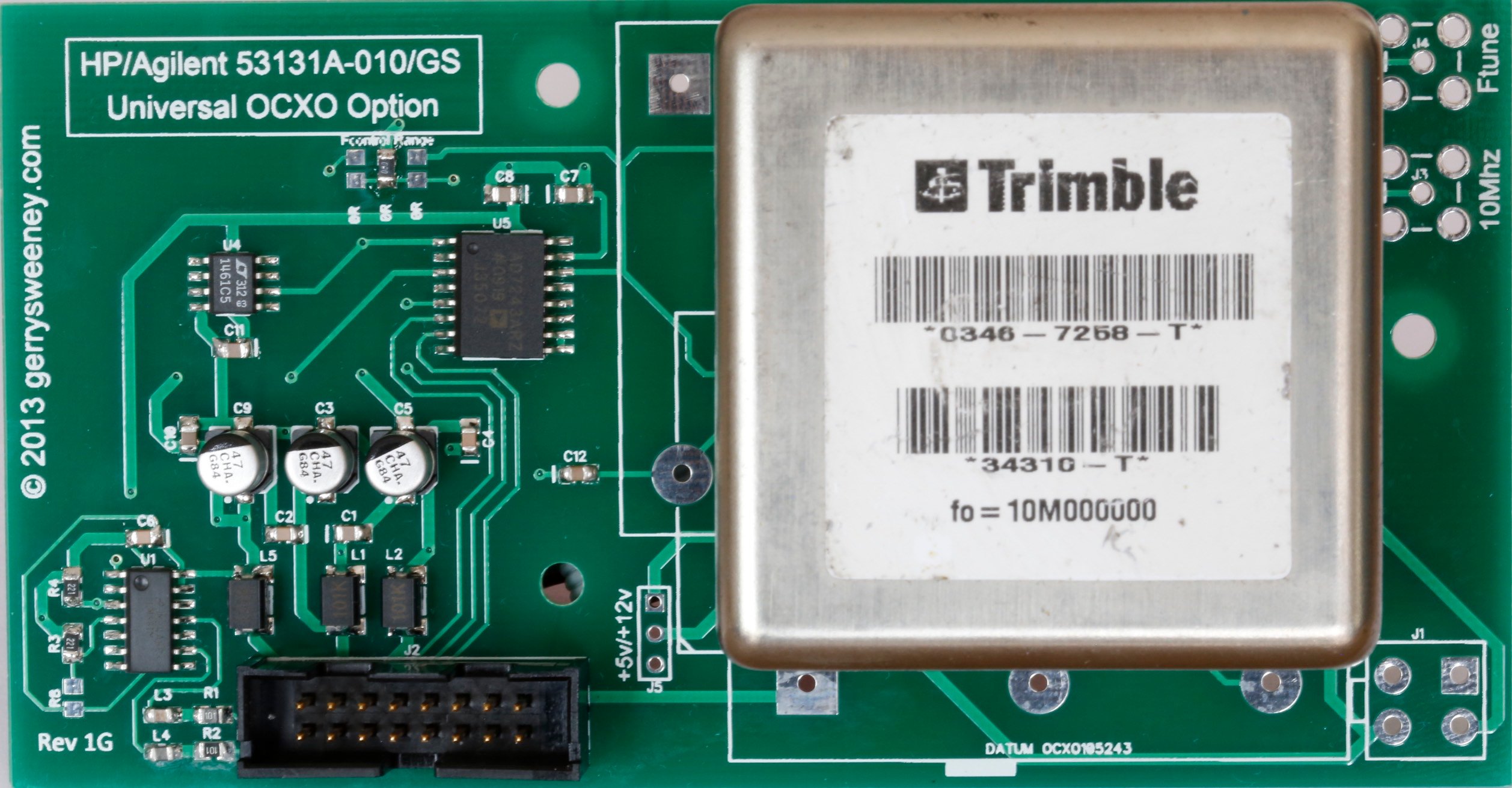
The PCB
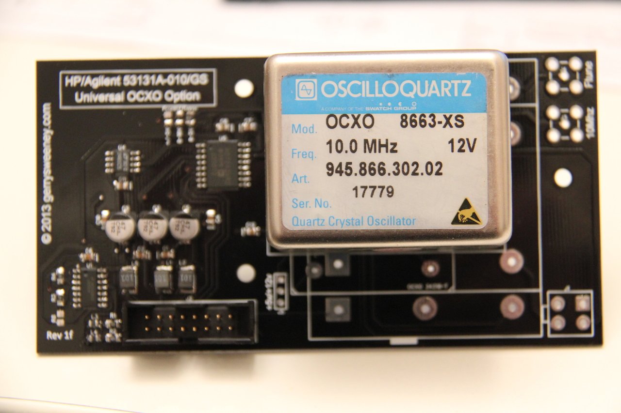
This is the revision “1F” board. When I designed the board, I picked a few of the OCXO types that are available on the second-hand (salvaged) market and designed it to accommodate these. My original plan was to support four types of OCXO, the Oscilloquartz 8663-XS that I used in my own counter, a Datum 105243-002, and Isotemp OCXO-131 and a Trimble 34310-T(2). However, when I laid the board out I did not have the Trimble 34310-T(2) device to hand and made a (wrong) assumption about the footprint – which is a bad schoolboy error I know – the upshot being that while this board has a footprint and markings for the Trimble 34310-T(2) it does not fit, the pins are about 1mm out and therefore the board IS NOT suitable for that particular device. It is feasible to drill holes, the pads are just about big enough but assuming there is some demand for these boards I will order a second batch with the footprint corrected.
The following OCXO’s are known (and shown in the video) to work. Any others might work but thats up to you to verify 🙂
- Oscilloquartz 8663-XS
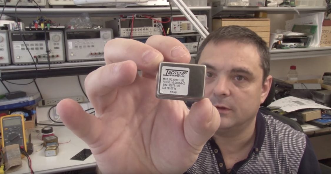
- Isotemp OCXO131-100
- Isotemp OCXO131-191
- Datum 105243-002
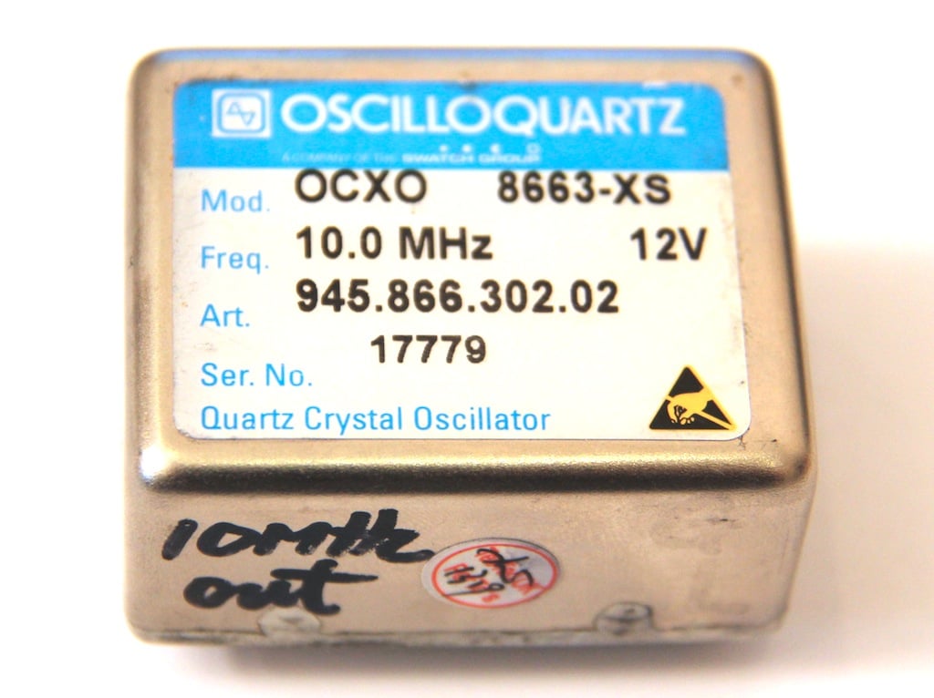
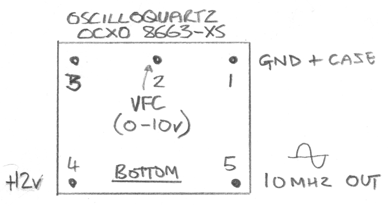
Oscilloquartz 8663-XS
This is the first OCXO I used, its more expensive than most and seems good quality and very precise. It works off of 12v and provides a nice clean sine wave output. The voltage control input works on the 0-10V range. I could not find any data on the XS version so I don’t know what its performance specifications are. I have included a download for this device but it does not cover the XS version specifically. The data sheet states that this device requires 0-10v for the frequency control, and testing seems to bear this out too. However, to get the counter to calibrate properly I selected the 0-5v range on the DAC.
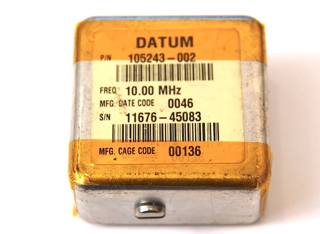
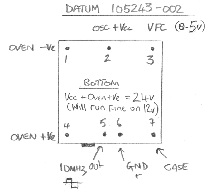
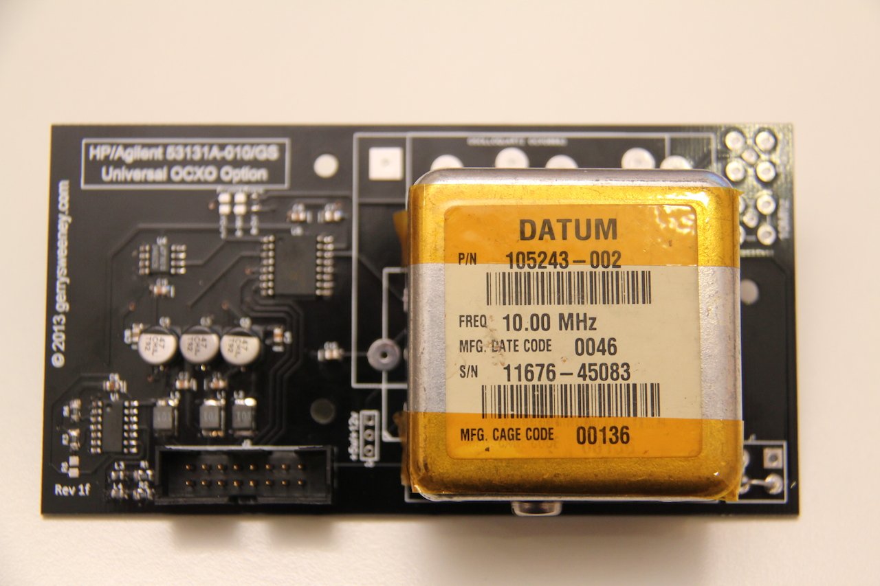
Datum 105243-002
This was another OCXO that I included on the board for Andy (who built the first 3Ghz pre-scaller option board), again a nice device but its specified to work on 24V and the Oven and Oscillator have separate power connections. This is the only OCXO that has a built in trim pot which allows you to set the window for the voltage control range. Although this device is specified to run at 24V, I tested its operation at 12V and it works perfectly. I did put a four-pin plug onto the board to allow you to give it a separate 24V supply but it really does not need it. I do not have any data sheet for this device but it outputs a square wave which is not as nice as having a sine wave on the output – but for this application it does not matter at all. The Frequency control input on this device is very sensitive and while it works without problem at +/-10v its centred around 2V and 0-5v works just fine.
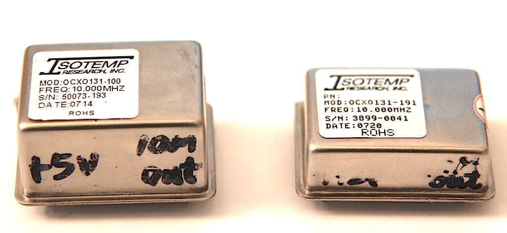
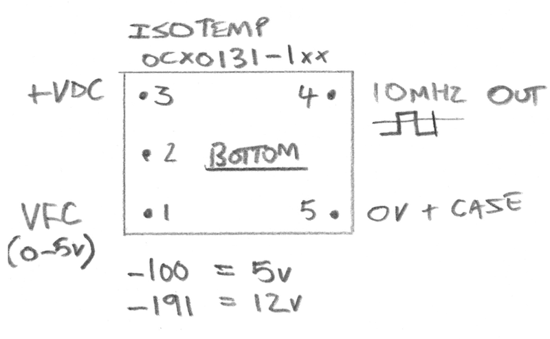
Isotemp OCXO131-1xx
This is a small, compact device and comes in two variants, the OCXO131-191 which is a 12V version and the OCXO131-100 which is a 5V version, and while both share the same PCB footprint and pinouts the case for the 5v variant is taller at 18mm high where as the 12v version is a compact 11mm high. These also provide a square wave output. Both versions of the device require 0-5v on the frequency control input although to get the counter to properly calibrate I had to configure it for the +/-5V option.
Kit of Parts
Some people asked me about providing a kit of parts. I am not really geared up to do that in a time-efficient way so apart from the bare PCB, I will not be able to provide individual parts or components.
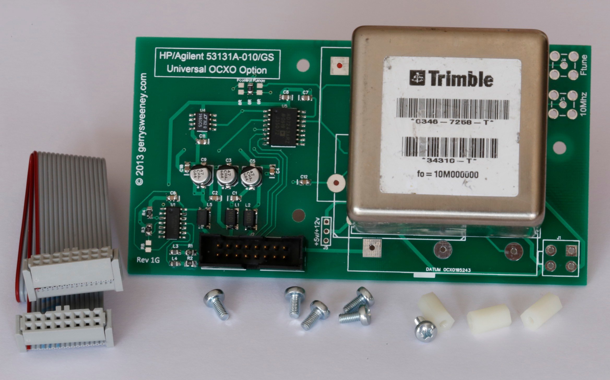
Fully Built and Tested Option
I am planning to have a limited number of these option boards fully built and tested with all the components and the OCXO pre-installed as well as a suitable cable and mounting stand-off’s, ready to install and use in your counter 531xx HP counter. I do not have an exact cost for these as I still have to source some of the components but they are likely to be be in the £75 to £95 range. I will post an update when I have these available which should be in about 2-3 weeks time.
UPDATE: I now have some fully assembled and tested boards complete with cable and mounting parts needed for a simple plug-and-play 53100 series counter upgrade. I am providing these with a Trimble 34310-T OCXO which is a really high quality, high spec double-oven OCXO, performance compares very favourably to the original high end option offered by HP at 10x the cost
Bill of Materials
| RefDes | Part No | Notes |
|---|---|---|
| C1, C2, C4, C6, C7, C8, C10, C11 | 100nF | 0805 SMD Jellybean part |
| C12 | 1uF | 0805 SMD Jellybean part – Could probably use 100nF with no problem |
| C3, C5, C9 | 47uF 16v | Electrolytic. Farnell Part No: 197-3305 |
| J2 | IDC2X8M | Farnell Part No: 231-0066 |
| L1, L2, L5 | 100uH | Farnell Part No: 935-8056 |
| L3, L4 | 1uH | Farnell Part No: 221-5638 |
| R1, R2 | 100R | 0805 SMD Jellybean part |
| R3, R4 | 220R | 0805 SMD Jellybean part |
| R8 | 220R | 0805 SMD Jellybean part – This is not needed unless you want to mess with the comparator bias |
| U1 | LM361M | Very fast differential comparator |
| U4 | ADR4550 | You can use a REF02 or numerous other 5V reference parts here, the pinout is pretty standard |
| U5 | AD7243AR | This is the most expensive and hard to get part |
Bare PCB’s Available
UPDATE: After my first trip to the post office today I have had to amend the pricing because of the outrageous postal charges, I have been told that I cannot send something that’s not made of paper as a letter! that means for my friends outside of the UK the postage is more expensive, sorry about that. The good news is, the postage does not go up with the number of boards. I hope you understand.
UK Orders
If you want more than two boards please contact me directly via e-mail because the weight starts to impact postage.
| STILL AVAILABLE 1 x HP/Agilent 53131A-010/GS OCXO Option Bare PCB Rev 1H inc. Postage | £12.50 | |
| STILL AVAILABLE 2 x HP/Agilent 53131A-010/GS OCXO Option Bare PCB’s Rev 1H inc. Postage | £23.00 | |
| UNAVAILABLE HP/Agilent 53131A-010/GS Rev 1G Fully Built and Tested with Trimble 34310-T OCXO, Cable and Mounting Kit | £145.00 + £10.00 shipping (tracked and signed for) | Contact Me |
Non-UK Orders
If you want more than two boards please contact me directly via e-mail.
| STILL AVAILABLE 1 x HP/Agilent 53131A-010/GS OCXO Option Bare PCB Rev 1H | £15.00 | |
| STILL AVAILABLE 2 x HP/Agilent 53131A-010/GS OCXO Option Bare PCB’s Rev 1H | £27.50 | |
| UNAVAILABLE HP/Agilent 53131A-010/GS Rev 1G Fully Built and Tested with Trimble 34310-T OCXO, Cable and Mounting Kit | £145.00 + £18 shipping (tracked and signed for) | Contact Me |