My 2010 27″ 1TB iMac ran out of disk space because of the video content I was creating. Despite Apple’s best effort to limit my upgrade options I manage to upgrade it to include a 250GB Solid Sate Drive (SSD) plus a 2TB Hard Disk Drive (HDD) and get my system back to its last working state but with lots more disk space and much faster boot and application load times. Plenty of gotcha’s along the way – I had to work out and do a few ad-hoc adaptations. I cover new disk preparation, computer tear down, SATA adaptation, HDD temperature sensor hack and data moving, and data and account recovery.
This is the longest video and the longest blog article I have written to date, and thats reflective of how much there is to cover – is not a simple task.
I removed a Seagate Barracuda 7200 1TB drive which is still in working condition, despite being one of the drives on a recall by Apple. They offered to replace the drive some time back but I refused as it was inconvenient to be without my computer for a week, let alone the hassle of taking it to and collecting it from an apple store.
I installed the following components.
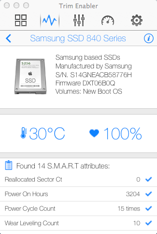
- Samsung SSD 840 Series 250GB
- Western Digital Green 2TB – 6 Gb/s 64Mb Cache
- SATA 90 degree Cable
- SATA Power Splitter
The 2TB drive was a perfect physical fit but did not have a compatible on board temperature sensor so I had to fashion one from a transistor, I used a TO-92 2N2907 and used the base-emiter junction as a silicone temperature sensor. The SSD drive had to be installed with double-sided tape but being so small and light this was the best solution. The whole modification to the computer is 100% reversible.
WARNING: This is an EPIC video at 1hr 20mins so only watch if you are really interested and have some time on your hands 🙂
The following outlines the various commands and steps I took to make this work. I am not saying this is either the only way or the right way, its the way I used and it worked for me. The most important thing I wanted to achieve was to preserve all of my data and never have a single point of failure for my data throughout the entire procedure.
Before we do anything we must ensure that…
- The computer is in a working state.
- Have a *FULL* backup of the system – in my case this was on an Apple Time Capsule
- Ensure the current system has *all* software and OS updates applied.
- Ensure that you are logged in and have administrative rights on the account you normally use
Tools Used
- Intergral Hard Disk Copy Station
- T8 and T10 Torx Drivers
- Stanley Knife
- FindSpace Utiltiy Application
Prepare SSD Drive
- Using the drive copy station, connect the SSD drive to the computer via USB
- Choose “Ignore” when you are prompted to initialise the disk you just connected.
- Using the Applications/Utilities/Disk Utility create a single partition on the drive – use all default options, call the volume “OS Boot” or other name you will recognise or makes sense to you
- Run the OSX Mountain Lion Installer application
- When shown the drive to install on, press the Show All Disks button and select the drive you just created a partition on
- During the install follow all instructions as if you are doing a new OS install, once complete it will want to re-boot, let it do what it wants. Eventually it will boot to your new drive
- During the installation it will want you to create the administration account, call this “Admin” or something else you do not already have on your current system.
- Don’t worry, your existing drive will still be intact. Once you have booted from the SSD drive and verified its OK, shut down the computer unplug the SSD and re-start, it will boot to the original drive once again.
Prepare New HDD Drive
- Connect the new drive to the USB using the drive copy station
- Choose “Ignore” when you are prompted to initialise the disk you just connected
- Using the Applications/Utilities/Disk Utility create a single partition on the drive – use all default options, call the volume “Users”
- You should now see your new 2TB disk in finder, the disk should be empty.
Now we need to create a temporary account to unlock your profile so we can copy your home folder to the new drive.
Create a temporary Admin Account
- Open System Preferences/Users & Groups
- Unlock the panel if required
- Add a new user, in the New Account field select Administrator
- Log out of the system, and log back in using this new account you have created
At this point you are ready to make a copy of your user profile(s) from your existing 1TB disk to your new 2TB disk. Open a new terminal window (Applications/Utilities/Terminal). You can list the accounts on your system by issuing the following command: –
ls -li /Users
For each account on your system that you want to re-locate to the new 2TB drive you should issue the following command: –
sudo ditto -v /Users/<ccount_name> /Volumes/Users/<account_name>
You should obviously replace the <account_name> part with the account name. In my case the command was: –
sudo ditto -v /Users/gerrysweeney /Volumes/Users/gerrysweeney
NOTE: You do NOT want to make a copy of the temporary admin account you created earlier that you are currently logged in as…
Do the hardware hacking
At this point you are ready to start the disk transplant process. You want to do the following things in order.
- Shutdown the computer cleanly
- Unplug all cables
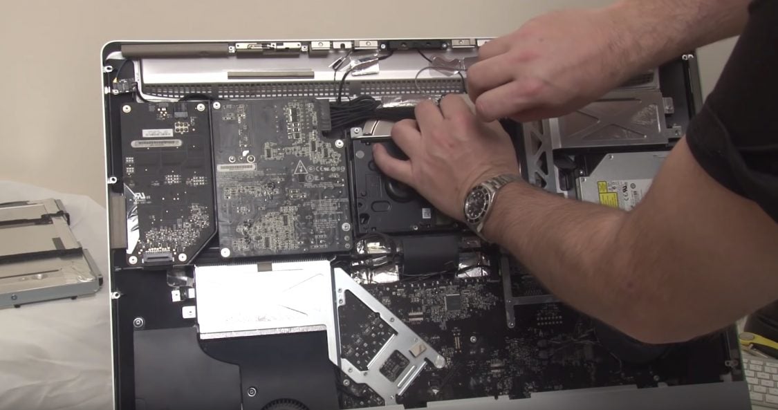
- Take the computer apart and remove the 1TB hard disk
- Transfer the mounting braket and studs from the 1TB drive to the new 2TB drive
- Put the old 1TB drive into an anti-static back and put in a safe place – this is your fast recovery/back-out plan
- Remove the optical drive, screen backlight supply and main power supply boards, and then the main board – see video
- Install the new SATA cable for the SSD drive – either use the third SATA port or remove optical drive SATA cable and use that port – depends on your iMac model
- Replace the main board and PSU baords, take a lot of care routing the new and existing cables, there is very little room for error here
- Install the SSD drive using double-sided sticky pads – make sure its well fixed, you do not want it coming loose as it will interfere withe air flow that cools the GPU – this will Kill your iMac!!
- Re-install the optical drive (with or without being connected), the drive carrier acts as part of the air ducting…
- Install the new 2TB drive
- Fashion a suitable temperature sensor for the new HDD, I simply used a 2N2907 transistor which works a treat from what I can tell
- Re-assemble the computer
- Power up and make sure it boots to the new SSD drive
- Log into the “admin” account you created – this should be the only account on the system
If all has gone well you should have a fresh new OS and you should be logged in as administrator. The next thing we need to do is re-create the accounts and then re-locate their home directory.
Follow these next steps carefully…
First of all you need to create a new account for each account you have re-located. In my case the account I relocated is “gerrysweeney”. So go into the System Preferences/Users & Groups tool, unlock it if needed, then create the new account. By default, this will create a new account home folder on the SSD, thats OK, we will need to deal with that next. If you have more than one account you have re-located, create a new corresponding account for each one. When you create the account, use the same password as your previous account, this way your keychain will remain accessible and valid once you re-instate your home folder.
Now you have a new account with a new home folder on the SSD drive, the next thing is to modify that account and point it to the home folder you previously re-located. In my case the account was “gerrysweeney”. In the Users and Groups tool, press the “Ctrl” key and click on the account name, you should get a menu option called “Advanced Options…”, select this. The “Home Directory” field will be set to “/Users/gerrysweeney”, you should change this to “/Volumes/Users/gerrysweeney”. Again, do this for each account you have re-located.
UPDATE: Having done this I realised that later on I still have to set up a symbolic link to the home folder which is a couple of steps below. In lights of that you can simply skip the above step of modifying the account properties to re-locate the home directory. Once the symbolic link is in place it will work without doing this.
Now we need to change the permissions of each account’s home folder data to the account – this is important to re-syncronise all permissions. Open a terminal window and for each account you have re-located you should issue the following command: –
sudo chown -R gerrysweeney:staff /Volumes/Users/gerrysweeney
This command will change the ownership of every file in this folder, including the folder its self and all sub-folders and files. Now I am not sure this is exactly right, it is feasible there are system files that should be protected from the user but I don’t know – what I done worked OK so its pretty safe. In any case you need to do this for every account you have moved – remember to replace “gerrysweeney” with the right account name.
Now you have given the right ownership to your files, we now have to deal with the fact that much of your existing configuration will be looking for profile and other content from /Users/gerrysweeney, and the way we deal with that is by creating a symbolic link. In the terminal window you should issue the following command to delete the newly created home folder on the SSD drive that we no longer need.
sudo rm -rf /Users/gerrysweeney
Now you should create a symbolic link to map the expected home folder location to the relocated folder on the new 2TB drive. To do this you should issue the following command:
sudo ln -s /Volumes/Users/gerrysweeney /Users/gerrysweeney
You should do this for each account you have relocated. You can double check this operation worked by issuing the following command:
ls -li /Users
which should show you something like this...
total 8
 135869 drwxrwxrwt  13 root   wheel  442 13 Oct 20:22 Shared
 329606 drwxr-xr-x+ 13 admin  staff  442 14 Oct 10:18 admin
1056113 lrwxr-xr-x   1 root   admin   27 14 Oct 10:17 gerrysweeney -> /Volumes/Users/gerrysweeney
You can see that gerrysweeney is pointing to /Volumes/Users/gerrysweeney
The next thing we need to do is recover your applications. You have the option of simply re-installing them all but thats a right royal pain, I found this worked really well and mostly re-instated everything for me.
Get your original 1TB disk and using the Disk Copy Station connect to the computer via USB, you should be able to see this drive in finder. Make a note of the volume name for the drive – in my case this was “Macintosh HD”. In order to recover the applications, you basically need to copy all of your Library and Application Files to the SSD. To do this issue the following commands: –
  ditto -v /Volumes/Macintosh HD/Library /Library

  ditto -v /Volumes.Macintosh HD/Applications /Applications

  ditto -v /Volumes.Macintosh HD/Developer /Developer
Now with all that done, you should eject the original 1TB HDD using Finder and you should shutdown and re-start the computer. While re-booting you can unplug the Disk Copy Station, you should not need it any more.
At this point you should be able to log in using your original account – in my case this was “gerrysweeney”. If everything worked out OK then you will now have a working system, your desktop, applications and settings should all be restored and in the same state as they were before you started.
Set aside a day to do this, its a pain, there is a lot of fiddling around and there is a lot of waiting for stuff to copy. In the end though its a worthwhile mod that Apple does not want you to do.
Enable TRIM
UPDATE: I had found this after I finished the article and Anton pointed out in the comments I should include this information because it is important. Thank you Anton.
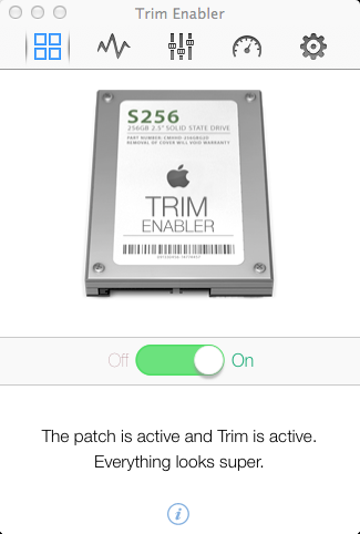
In order to maintain the healthy state of your SSD and prolong its life you need to enable the S.M.A.R.T features and make the OS and the SSD Drive communicate using the TRIM commands. This basically allows the OS and the SSD drive to play nice and help prolong the life of the SSD by minimising erase cycles, the OS simply informs the drives that blocks are no longer in use. Doing this is easy, you can simply install a piece of software called Trim Enabler which takes care of this for you. If you want to know more about TRIM you can read this wikipedia article
IMPORTANT DISCLAIMER
DO THIS AT YOUR OWN RISK. I HAVE PROVIDED THIS ARTICLE IN THE HOPE THAT IT WILL BE USEFUL FOR OTHERS. HOWEVER, YOU SHOULD KNOW THAT OPENING YOUR COMPUTER INVALIDATES ANY WARRANTY YOU MAY HAVE AND WHILE THIS APPROACHED WORKED FOR ME, IT MIGHT NOT WORK FOR YOU AND IF IT ALL GOES WRONG FOR YOU I CAN NOT BE HELD RESPONSIBLE. THERE ARE LOTS OF DELICATE AND SENSITIVE ELECTRONICS THAT ARE EASILY DAMAGED IF YOU DO NOT HAVE EXPERIENCE HANDLING THEM – PLEASE ONLY DO THIS IF YOU ARE CONFIDENT IN YOUR OWN ABILITIES