DIY HP/Agilent 53131A-030 3GHz Channel 3 Option Board

As part of the process of upgrading my counter to have a DIY high stability OCXO (Oven Controlled Crystal Oscillator), someone who watched my videos had designed a DIY 3GHz Channel 3 53131A-030 option board. The original from Agilent is very expensive (obviously) and there are clones you can get on e-bay which are a quarter of the price Agilent charge which is why he decided to design his own. His name is Andy and when he saw my video’s he got in touch and offered me one of the PCB’s to which I of course said YES PLEASE 🙂

Now as it turned out, when Andy constructed his own board he had enough components left over so also constructed and tested one for me which was a really kind thing to do and very unexpected too. In exchange for this I have insisted that I can build him an OCXO board while I am doing mine to return the favour.

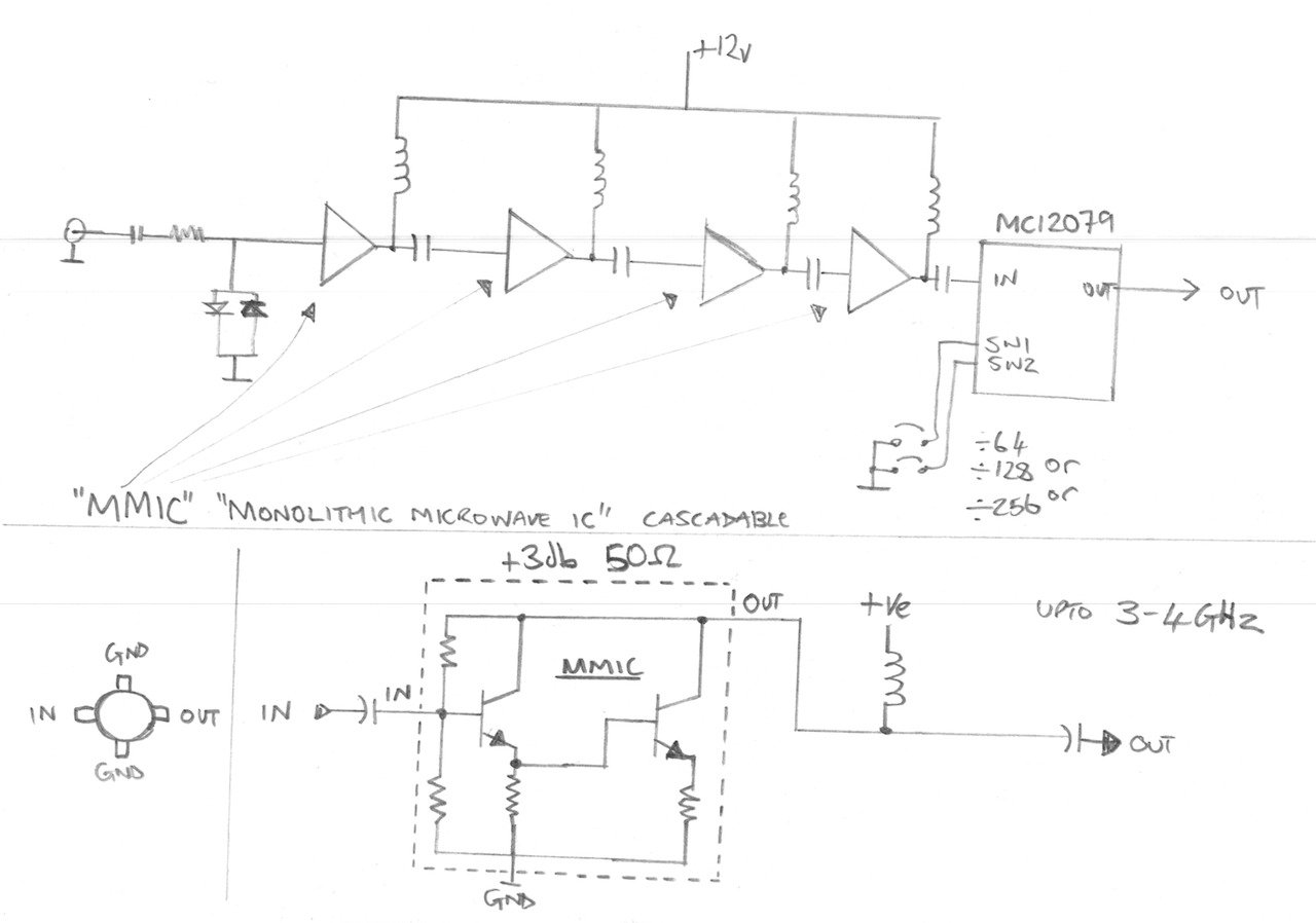
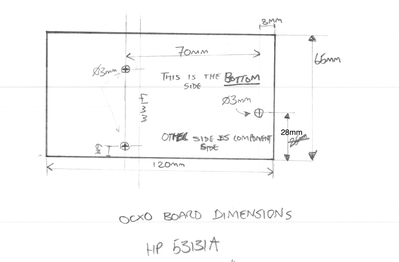
Anyways, I thought I would do a video to show the HP/Agilent 53131A-030 DIY 3GHz Cannel 3 Option board getting fitted to my counter. I also spend some time explaining how the pre-scaller circuit works and in basic terms what MMIC’s are and how they work too. I also make an adaption to my previous hard power switch modification to make way for the upcoming DIY OCXO board, and I measure up to get the exact board dimensions and mounting hole positions I need for the OCXO PCB layout.

The entire work and full attribution for the DIY 030 option board/PCB goes to Andy, so Andy – thank you so much for making one of these for me – I really appreciate it.

PLEASE NOTE: I will not put Andy’s Youtube/EEVblog ID here unless he asks me to, and I will not pass on his details without his express permission so please don’t ask – I respect people’s privacy. If Andy does want to share his details in connection with this project then I will gladly put them here.

PLEASE ALSO NOTE: The schematic drawing below is technically incomplete and is meant as an illustrative block diagram. In the real circuit there is also a resistor in series with each inductor at the top of each MMIC to set up the right DC conditions.

See you next time.

HP 339A Teardown

A piece of equipment I use rarely but when I do I find really useful is my HP 339A Distortion Measurement Set. Built in the 70’s this unit has a precision sine wave oscillator and distortion measurement section. One of the things thats really nice is the oscillator and the notch filter are tied together and the notch filter auto-nulls to make measurements really easy to accomplish.

The build quality of this unit is impeccable, made by HP when they were making stuff properly. The entire chassis is made from folded high quality aluminium sheets with capture nuts and really precise machining. The main oscillator switches are coupled using a bar and wafer scheme but both the oscillator and the filter are fully screened and isolated in their own chassis sub-sections. The smell from inside the unit is that old-school electronics smell I used to encounter all the time when I was a kid taking apart old TV’s and Record Players. I don’t know what chemicals exactly make that smell but I am pretty sure if you could bottle it you could sell it – there is an idea for a unique aftershave! It could be called “Ye’old TV Man”!

Anyway, hope you will find the video interesting. Thanks for watching.

Measuring Distortion with a HP 339A and a Keithley 2015 THD

I have had my HP 339A for a long time now and despite only using it a small handful of times it is a really great instrument – but – its big and takes up a lot of shelf space. A few weeks back a purchased a Keithley 2015 THD which is a 6.5 digit bench meter with a built in distortion analyzer, I bought it because of the distortion analyzer function. I would like to get some more instrument shelf space back so am able to replace the HP 339 with this 2015THD I will make that much-needed space. I decided to build a simple output circuit so that I can induce some crossover distortion and compare the basic measurements on these two devices to see the results. Now I must make it clear that this is a basic 101 on measuring distortion, I am sure there is a lot more to know that I do but I believe I cover off the basis.

The simple drawing I used to explain the test and test circuit.

I will tear down the HP 339A on video to show how nicely these are built. This is one of those rare “all analog” devices that has not digital parts at all, watch out for that video if you like seeing the guts of nicely built equipment.

Thanks for watching.