The project is focused on creating a high-quality bench power supply that is modular in construction and easy to build for the DIY’er but will offer features more often found on professional equipment.
Articles
Part 1 – Project Overview
Part 2 – First Regulator Tests
Part 3 – A working regulator (with stability issues)
Part 4 – A working constant voltage, constant current regulator
Part 5 – Range and resolution calculations and tables
Part 6 – Current Affairs and Sensitivity
Part 7 – DAC Attack!
Part 8 – ADC meets DAC and some video to prove it!
Part 9 – Programming resolution achieved – and then some
Part 10 – First PCB and more improvements and circuit changes
Part 11 – Significant Design Changes for more Precision
Part 12 – The first PCB and Thermal Management
Part 13 – More design changes and measurements
Part 14 – Dynamic Response Improvements and Measurements
Video
View the YouTube video playlist for the project
Photo’s
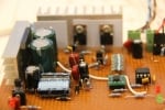
PSU Version 0.4a
This content is published under the Attribution-Noncommercial-Share Alike 3.0 Unported license.
Hi Jerry,
I am very much interested in your fully programmable modular bench power supply, what are the specs like max output voltage, max current, what is the cost of assembly? It’s just a hobby but I am impressed by what I saw.
Thanks,
Max
Hi Max,
I did not complete the PSU, I only got as far as Part 14, its on the list to continue. Check out the earlier parts on the blog, I spec’d out the ranges I was aiming for in the design. I did not really work to a budget in the end, it was more of an academic exercise for me to learn about DC regulator designs. Some of the parts are expensive, although you can sacrifice precision for cost quite easily. I should probably design a budget PSU because a lot of people ask me that question.
Gerry
Hi Gerry,
Thank you for all videos and posts that you have published. It is a great knowledge resource for me. Recently I did some experiments on your great design with a goal to optimize the cost and increase flexibility.
It seems that by replacing OPA2277s with precision rail-to-rail opamp I’ve managed to simplify your design without affecting performance. Some LTspice simulations and tests I’ve done with LTC6078 show excellent voltage and current precision from 0mV up. It is msop part and was hard to solder so for my next prototype I plan to use quad OPA4180 available as SOIC. It is about the same price as single 2277. With all negative supplies gone it is hard to think that further simplification can be made.
When it comes to whole PSU module single integrated board is very nice to have but I’m planning to make separate PCB for MCU, DACs & ADCs. Similar to your earlier prototypes.
I’ve found that couple smaller boards from china are cheaper than one larger. But mainly because this will allow many controllers with varying capabilities to suit different needs. With separate building blocks whole PSU project could be started with analog board driven by couple pots. At later stages simple upgrades can be made to full version.
To further increase flexibility (and reduce pcb size & cost) I decided to remove bulk caps and bridge rectifier from the board. They are easy to add with couple wires. My plan is to move them to additional board with relays to switch taps on the transformers. I also plan to use switching power supplies I have from old laptops and bridge rectifier is definitely useless for that 😉
Hi Tom,
My original implementation also used rail to rail single supply op amps an dI tried really hard to make it work but I was never happy with the performance, I could not get 0.001v out if programmed, I had the resolution but although the op amps will go to the rails they de-linearise at the edges and things did not work out, I very reluctantly added the -ve supply into the design but was glad I did, precision became a whole lot simpler to achieve. I like the modular approach but ultimately I felt it was a good challenge to squeeze everything onto one board and engineer out any inaccuracies due to voltage drops across wiring at high currents – that was my thinking at the time at least.
Gerry
like your work!
a schematic for a budget programmable PSU would be awesome.
Cheers!
Hi, budget and programmable are quite difficult to combine. Perhaps you can expand on your thoughts? Gerry
Hello Gerry. Do you intend to make the firmware/software available some time in the future?
Thank you.
HiTed,
Yes I did intend to, I need to strip out some non-open-source elements before I do that and have not gotten around to doing that so far. To be honest though the firmware for the most part is geared towards test/development, its not really the finished article.
Gerry
Hi!
Do you have any spare pcb’s to sell, or Gerber files ? And I’m also interested in the firmware in the pic.
I’m planning to make a lipo charger for some special batteries I make for my quad.
Hi, I am afraid I do not have any PCB’s available for sale, I only had a small number made for prototyping. Gerry
I watched and learned so much from this fantastic blog post. Thank you.
Unfortunately, every design I’ve found (with the exception of EEVBlog), has left me hanging at the end! The authors just lost interest, or it became too much, or they decided not to publish their code, or….
I would’ve loved to build your design and learn even more, but it looks like that will not happen.
Back to the search… I am super sad 🙁
Hi Mai,
Sorry about that. The design is finished electrically, its sound and it works very well to the best of my understanding. I was not happy with the physical construction which is why the project stalled, I did have the next PCB version delivered but have not yet built one. The software is not really in a usable state and most of it was running on a computer written in Qt/C++ and I was also using a couple of commercial libraries for rapid development so I was not able to release the code. Time I am afraid has been my problem, work commitments have taken priority I am afraid because thats ultimately how I pay the bills and feed my kinds 🙁 I am sure at some point I will pick up the project and do more with it, but even in its unfinished state I would hope there would at least be some useful content and learning for people.
Gerry
I’ll be waiting for return. Use much of what you showed in my own electronic load, you really explained and showed a lot, thanks!
Hiya, I’m really glad I’ve found this info. Today bloggers publish just about gossips and internet and this is really irritating. A good blog with exciting content, this is what I need. Thanks for keeping this site, I’ll be visiting it. Do you do newsletters? Can’t find it.
Hi Garry, I came across your excellent work as I’m interested in building something similar. However, I’m definitely going to exclude the PC software part as it should be stand alone. So the design I’m aiming for will have a full controller board and display. Your project looks like a great base to help me with my implementation.
Thanks for the feedback, I am glad the project helps. Good luck with the design.
Gerry