Update – DIY HP/Agilent 53131A 010 High Stability Timebase Option PCB’s Available

Update – DIY HP/Agilent 53131A 010 High Stability Timebase Option PCB’s Available

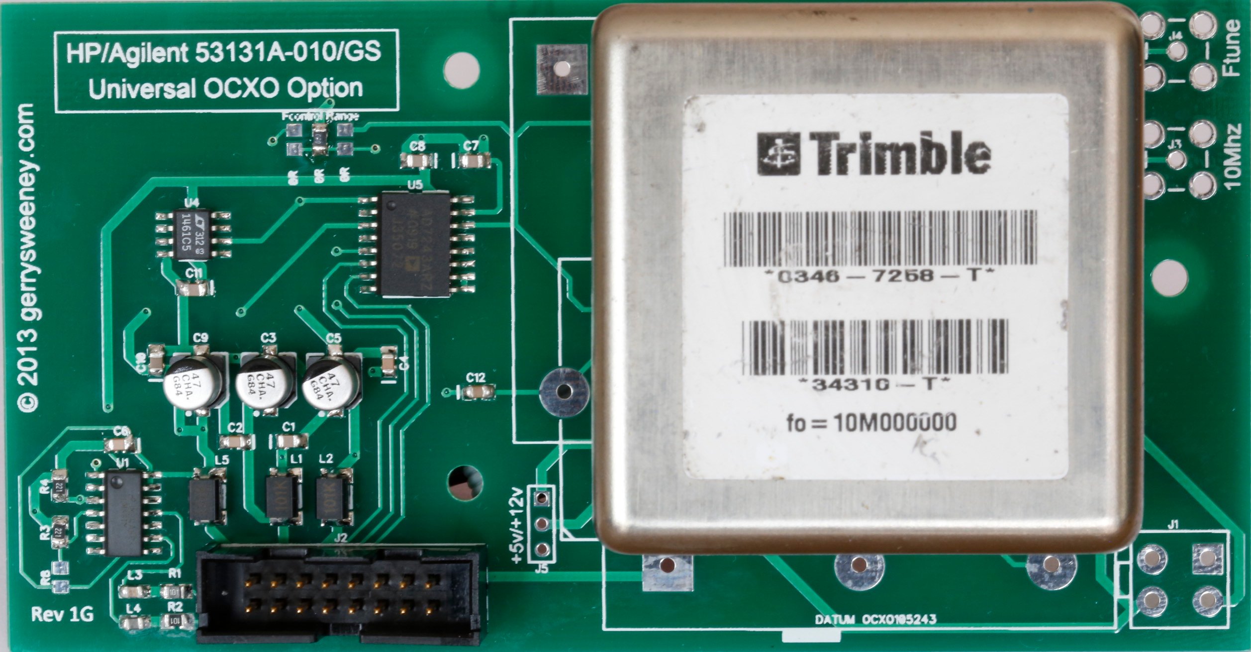
Following on from the project to build a DIY OCXO upgrade option for my HP/Agilent 53131A Frequency Counter I had a large number of requests for me to make the PCB’s available so others can built there own. I now have some PCB’s and are making them available for sale. I will also be making some fully assembled and tested/verified boards including an OCXO, ready-made cable and mounting stand-off’s, there will only be a limited number of these so if you are interested, let me know, first come first serve and when they are gone they are gone.

Now, someone made a comment on hackaday stating that the reason why these OCXO’s are on e-bay is because they are no good. Well I can understand why one could draw that conclusion but having now played with in access of 50 of these OCXO’s I can tell you that they all pretty much violently agree with each other and they also agree with the Rubidium Frequency Standard I have, so given they are from different sources and all free-running I am pretty comfortable they are good and usable quality devices. I read a lot on the net about “burn in time” and the general consensus seems to be, the longer you age and heat a crystal oscillator the more stable (in terms of drift) it becomes. Now I don’t know how true that is, but if it is true, then by definition, using recovered OCXO’s must actually be a good thing. Of course if you feel the need to pay a couple of hundred dollars for a new OCXO then you can of course do that – but I am pretty sure that it does NOT guarantee you any better performance, it just buys you the right to get compensated if you happen to find it does not meet the performance specifications quoted by the manufacturer and it might make you feel a little more confident. Anyway I guess the results speak for themselves and for a home lab these OCXO’s are more than good enough I think.

Here is a short video showing the various configurations built and working as well as a quick overview of the PCB its self and the configuration options.

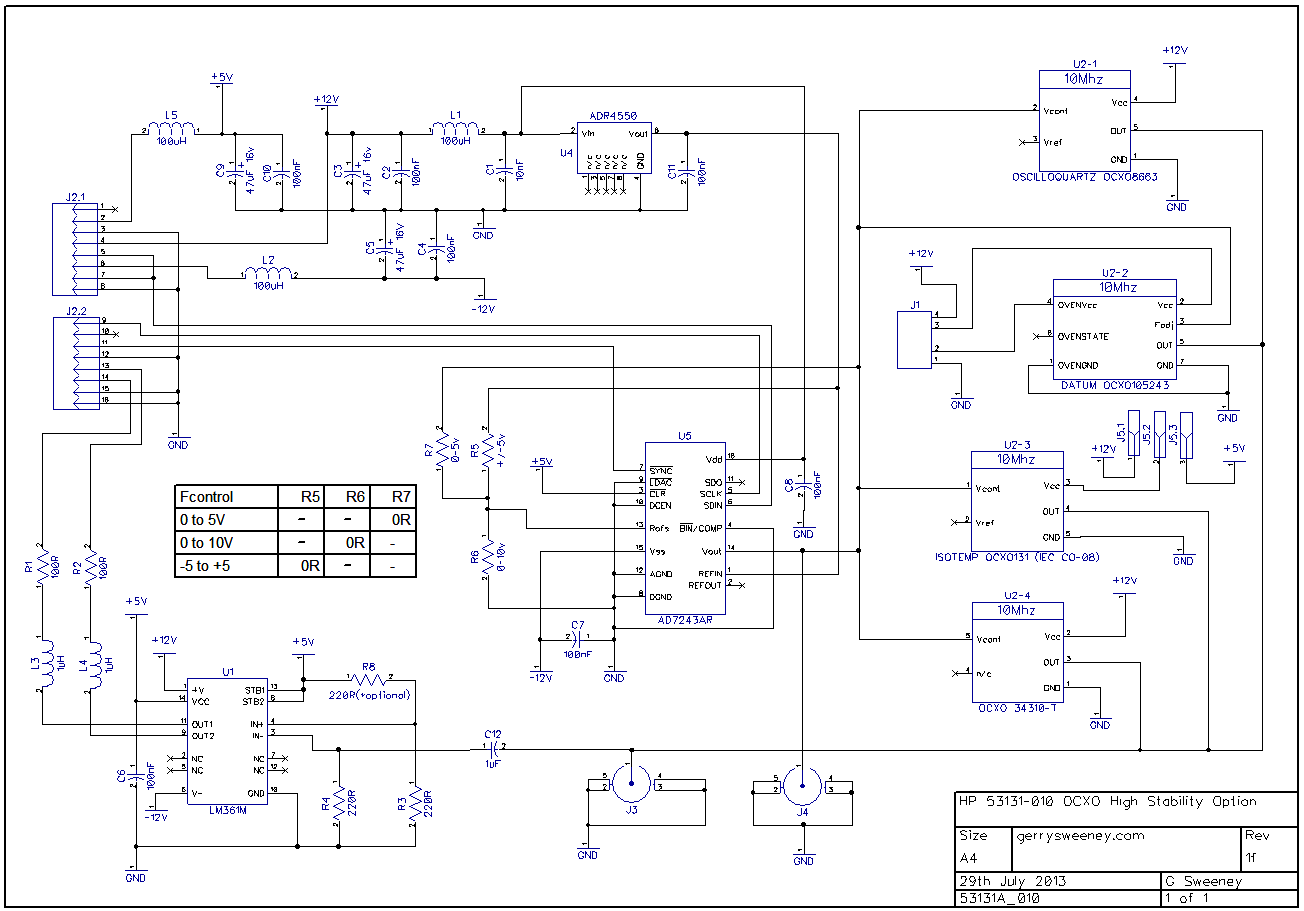
The Schematic

OCXO Rev 1F
53131A_010 Schematic

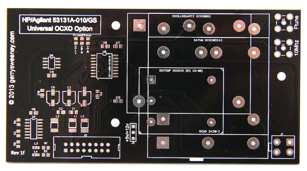
The PCB

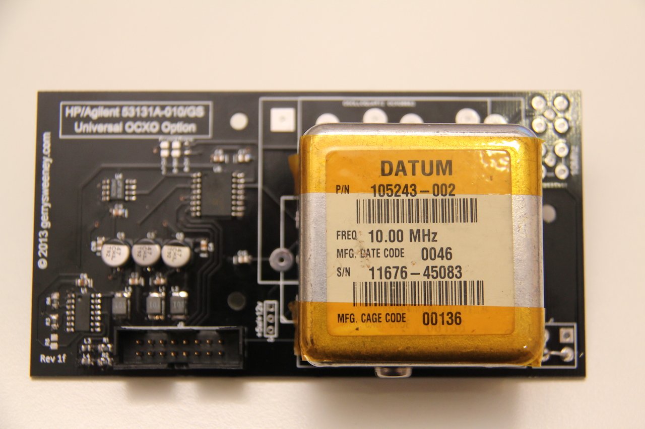
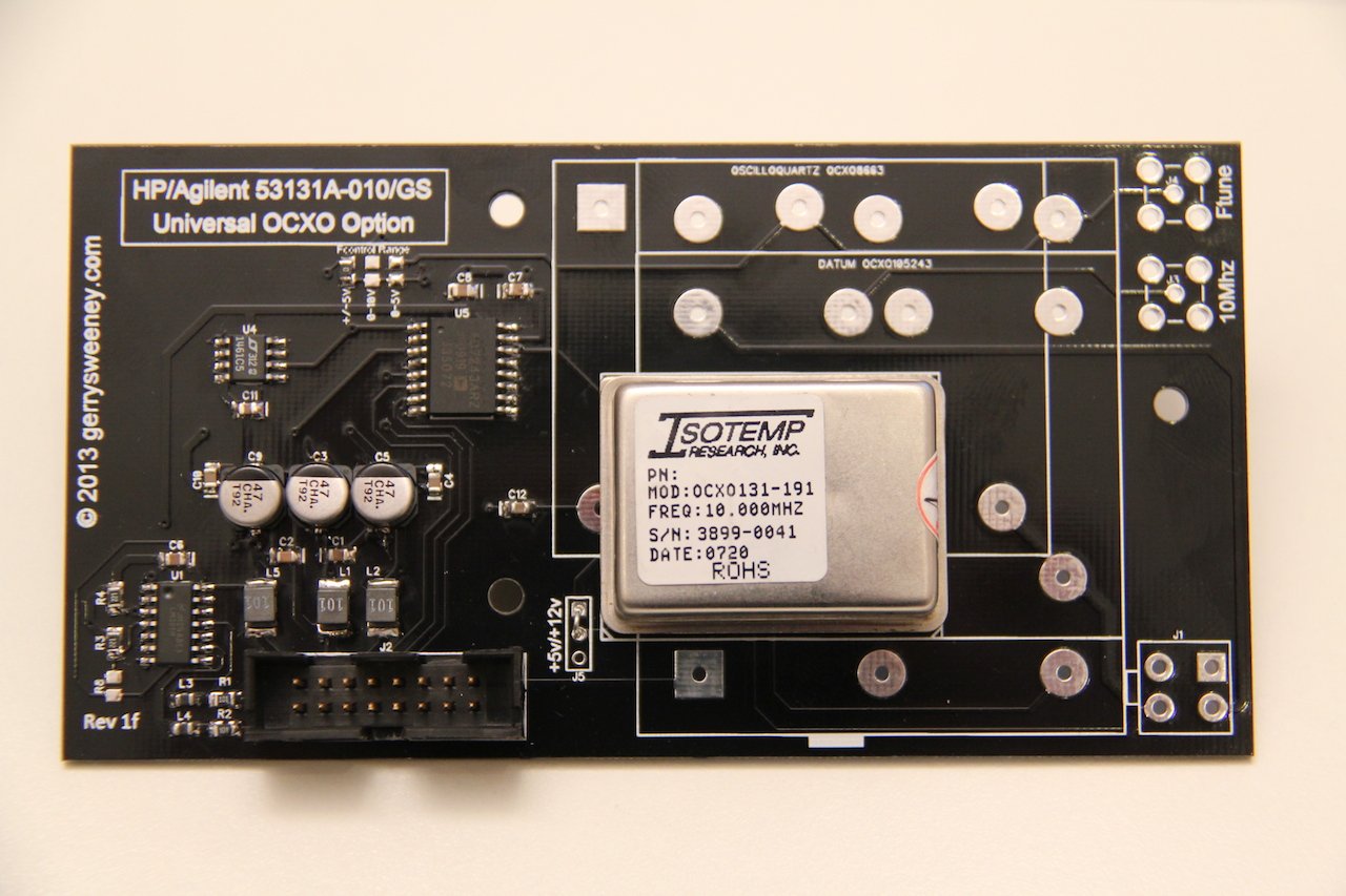
This is the revision “1F” board. When I designed the board, I picked a few of the OCXO types that are available on the second-hand (salvaged) market and designed it to accommodate these. My original plan was to support four types of OCXO, the Oscilloquartz 8663-XS that I used in my own counter, a Datum 105243-002, and Isotemp OCXO-131 and a Trimble 34310-T(2). However, when I laid the board out I did not have the Trimble 34310-T(2) device to hand and made a (wrong) assumption about the footprint – which is a bad schoolboy error I know – the upshot being that while this board has a footprint and markings for the Trimble 34310-T(2) it does not fit, the pins are about 1mm out and therefore the board IS NOT suitable for that particular device. It is feasible to drill holes, the pads are just about big enough but assuming there is some demand for these boards I will order a second batch with the footprint corrected.

|OCXOBoard-1f

The following OCXO’s are known (and shown in the video) to work. Any others might work but thats up to you to verify 🙂

  • Oscilloquartz 8663-XS
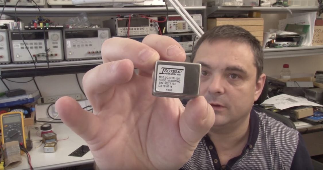
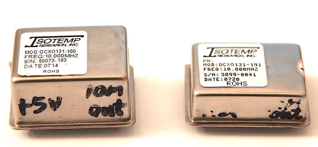
  • Isotemp OCXO131-100
  • Isotemp OCXO131-191
  • Datum 105243-002

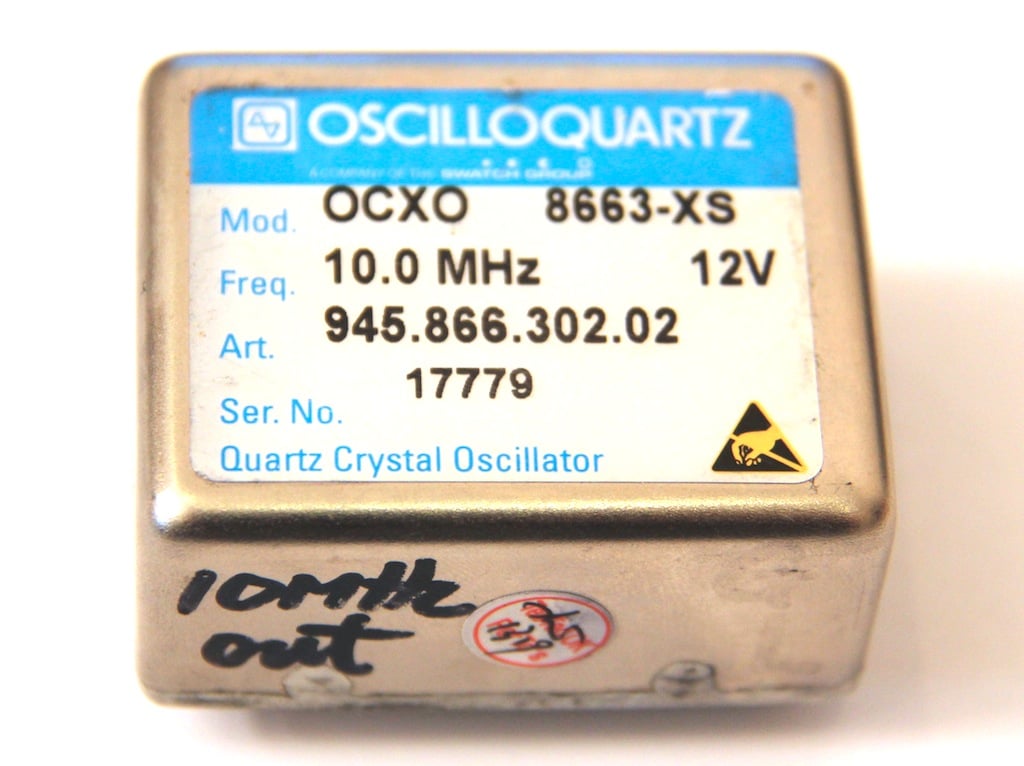
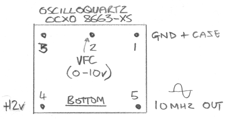
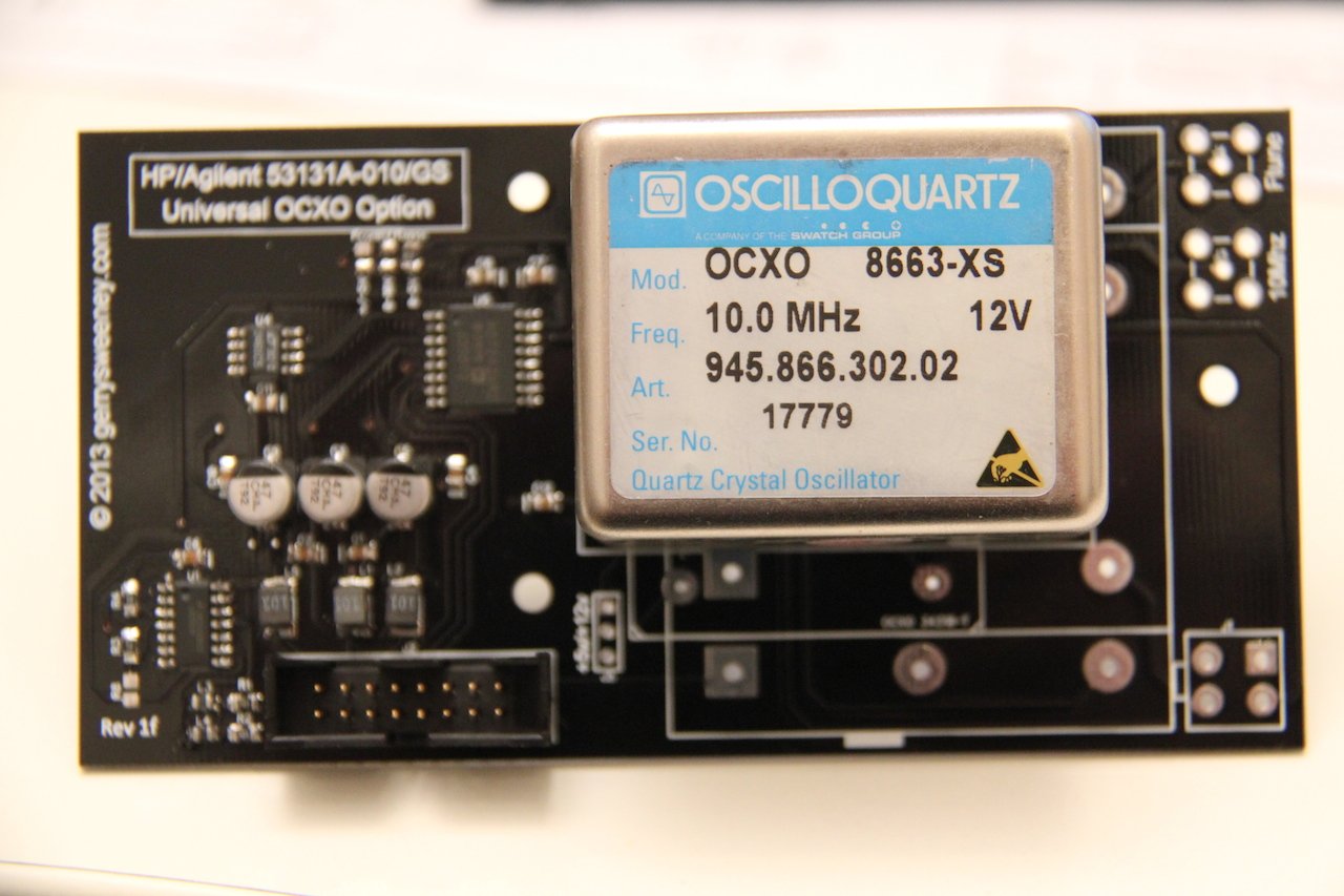
Oscilloquartz 8663-XS

This is the first OCXO I used, its more expensive than most and seems good quality and very precise. It works off of 12v and provides a nice clean sine wave output. The voltage control input works on the 0-10V range. I could not find any data on the XS version so I don’t know what its performance specifications are. I have included a download for this device but it does not cover the XS version specifically. The data sheet states that this device requires 0-10v for the frequency control, and testing seems to bear this out too. However, to get the counter to calibrate properly I selected the 0-5v range on the DAC.

Oscilloquartz  OCXO8663-pins

IMG_6182

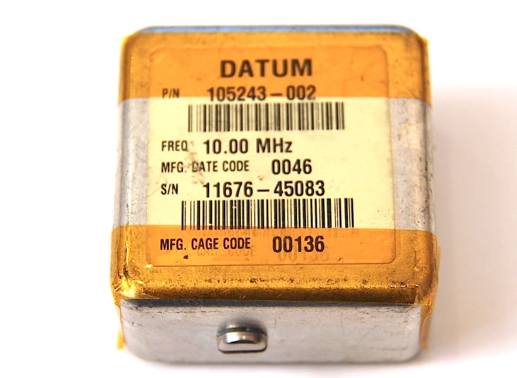
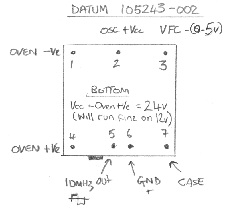
Datum 105243-002

This was another OCXO that I included on the board for Andy (who built the first 3Ghz pre-scaller option board), again a nice device but its specified to work on 24V and the Oven and Oscillator have separate power connections. This is the only OCXO that has a built in trim pot which allows you to set the window for the voltage control range. Although this device is specified to run at 24V, I tested its operation at 12V and it works perfectly. I did put a four-pin plug onto the board to allow you to give it a separate 24V supply but it really does not need it. I do not have any data sheet for this device but it outputs a square wave which is not as nice as having a sine wave on the output – but for this application it does not matter at all. The Frequency control input on this device is very sensitive and while it works without problem at +/-10v its centred around 2V and 0-5v works just fine.

IMG_6161  OCXO-DATUM-pins copy

IMG_6181

Isotemp OCXO131-1xx

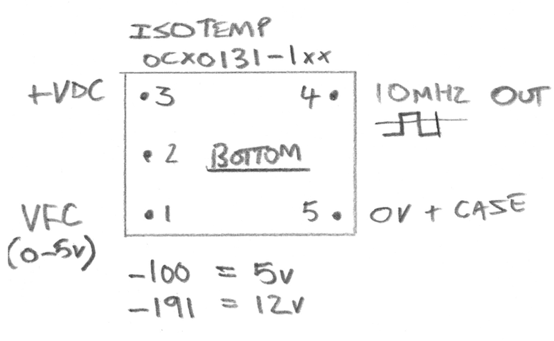
This is a small, compact device and comes in two variants, the OCXO131-191 which is a 12V version and the OCXO131-100 which is a 5V version, and while both share the same PCB footprint and pinouts the case for the 5v variant is taller at 18mm high where as the 12v version is a compact 11mm high. These also provide a square wave output. Both versions of the device require 0-5v on the frequency control input although to get the counter to properly calibrate I had to configure it for the +/-5V option.

Isotemp-ocxos  OCXO131-pins

IMG_6180

Kit of Parts

Some people asked me about providing a kit of parts. I am not really geared up to do that in a time-efficient way so apart from the bare PCB, I will not be able to provide individual parts or components.

Fully Built and Tested Option

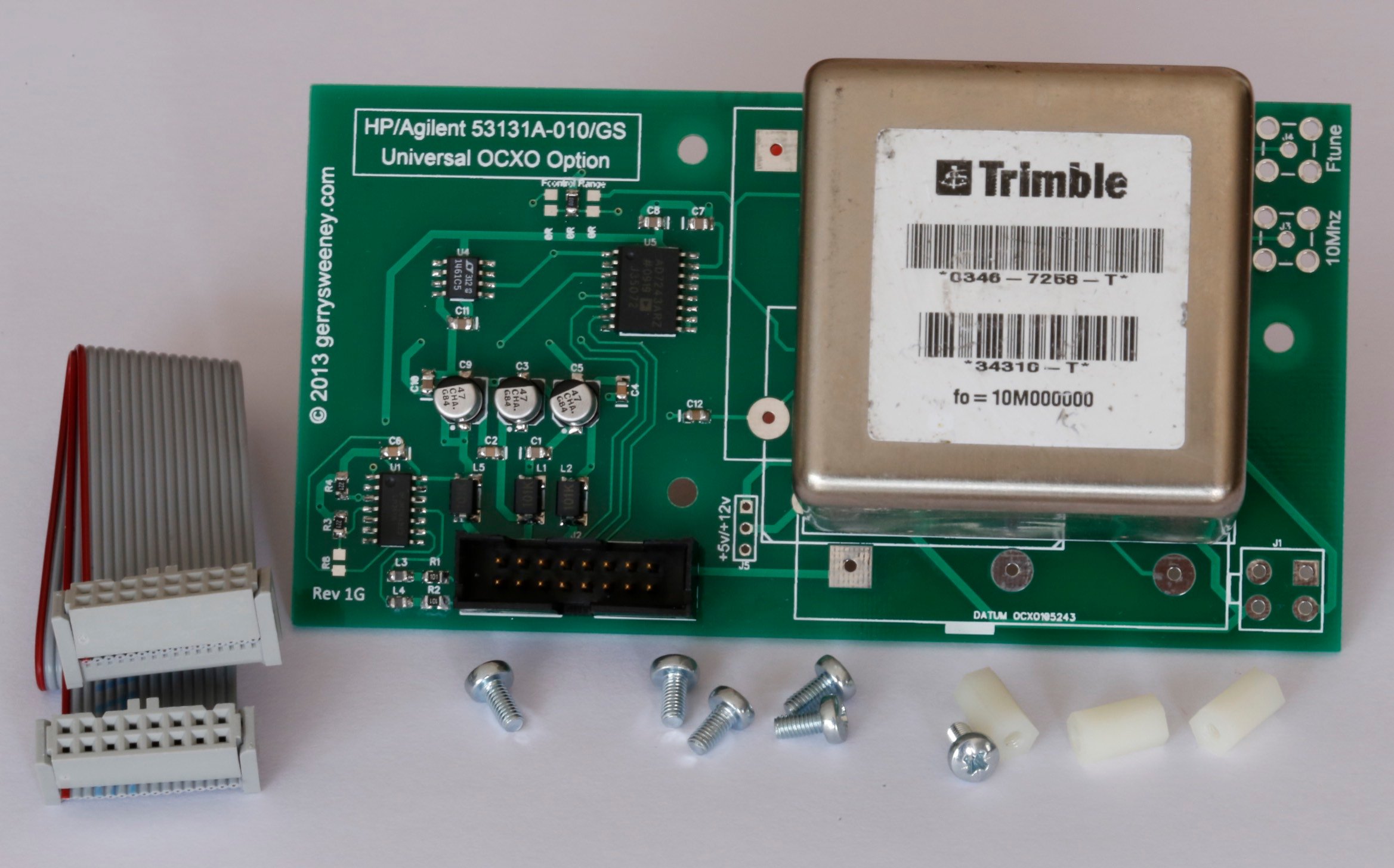
I am planning to have a limited number of these option boards fully built and tested with all the components and the OCXO pre-installed as well as a suitable cable and mounting stand-off’s, ready to install and use in your counter 531xx HP counter. I do not have an exact cost for these as I still have to source some of the components but they are likely to be be in the ÂŁ75 to ÂŁ95 range. I will post an update when I have these available which should be in about 2-3 weeks time.

UPDATE: I now have some fully assembled and tested boards complete with cable and mounting parts needed for a simple plug-and-play 53100 series counter upgrade. I am providing these with a Trimble 34310-T OCXO which is a really high quality, high spec double-oven OCXO, performance compares very favourably to the original high end option offered by HP at 10x the cost

_MG_9150

_MG_9141

Bill of Materials

RefDes Part No Notes
C1, C2, C4, C6, C7, C8, C10, C11 100nF 0805 SMD Jellybean part
C12 1uF 0805 SMD Jellybean part – Could probably use 100nF with no problem
C3, C5, C9 47uF 16v Electrolytic. Farnell Part No: 197-3305
J2 IDC2X8M Farnell Part No: 231-0066
L1, L2, L5 100uH Farnell Part No: 935-8056
L3, L4 1uH Farnell Part No: 221-5638
R1, R2 100R 0805 SMD Jellybean part
R3, R4 220R 0805 SMD Jellybean part
R8 220R 0805 SMD Jellybean part – This is not needed unless you want to mess with the comparator bias
U1 LM361M Very fast differential comparator
U4 ADR4550 You can use a REF02 or numerous other 5V reference parts here, the pinout is pretty standard
U5 AD7243AR This is the most expensive and hard to get part

Bare PCB’s Available

UPDATE: After my first trip to the post office today I have had to amend the pricing because of the outrageous postal charges, I have been told that I cannot send something that’s not made of paper as a letter! that means for my friends outside of the UK the postage is more expensive, sorry about that. The good news is, the postage does not go up with the number of boards. I hope you understand.

UK Orders

If you want more than two boards please contact me directly via e-mail because the weight starts to impact postage.

STILL AVAILABLE
1 x HP/Agilent 53131A-010/GS OCXO Option Bare PCB Rev 1H inc. Postage
ÂŁ12.50
STILL AVAILABLE
2 x HP/Agilent 53131A-010/GS OCXO Option Bare PCB’s Rev 1H inc. Postage
ÂŁ23.00
UNAVAILABLE
HP/Agilent 53131A-010/GS Rev 1G Fully Built and Tested with Trimble 34310-T OCXO, Cable and Mounting Kit
ÂŁ145.00 + ÂŁ10.00 shipping (tracked and signed for)Contact Me

Non-UK Orders

If you want more than two boards please contact me directly via e-mail.

STILL AVAILABLE
1 x HP/Agilent 53131A-010/GS OCXO Option Bare PCB Rev 1H
ÂŁ15.00
STILL AVAILABLE
2 x HP/Agilent 53131A-010/GS OCXO Option Bare PCB’s Rev 1H
ÂŁ27.50
UNAVAILABLE
HP/Agilent 53131A-010/GS Rev 1G Fully Built and Tested with Trimble 34310-T OCXO, Cable and Mounting Kit
ÂŁ145.00 + ÂŁ18 shipping (tracked and signed for)Contact Me

The Good, the Bad and the Ugly – Schematic and PCB Software

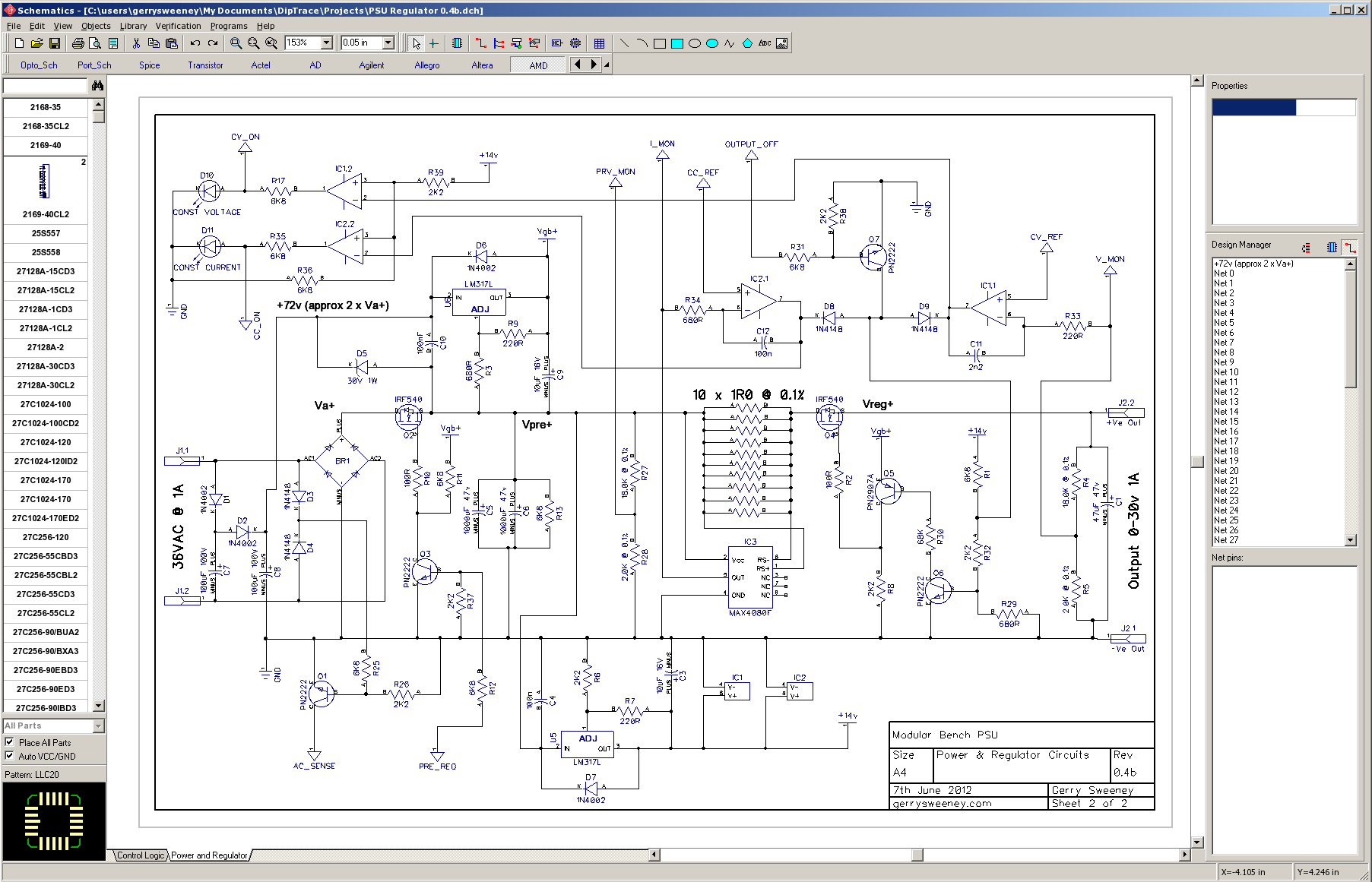
I have recently been using Diptrace for schematic capture and have just hit the 300 pin limit so I am looking at my options including alternative packages. Why am I looking at options? Having read numerous forums and reviews, based on other peoples experience it would appear that Diptrace is an improvement over Eagle and other low end solutions, I have tried Eagle In the past and I would have to agree, but Diptrace far from perfect, in fact its so poor in some areas I am now thinking about sinking time into evaluating other applications. Perhaps the EDA/CAD world has lower expectations that I do but even Diptrace which would appear to be the more intuitive of the bunch, the user interface, and more specifically the usability really sucks, it could be Sooooooooo much better.

Diptrace Screenshot

First of all, Mac OSX support. They claim it runs on Windows and OSX which is true. But on OSX its actually running the Windows version of the software under a windows emulator called WINE. Worse than that, WINE runs under Quarts X11 which is yet another layer of abstraction before it hits the actual screen. Trust me, the thing is crappy, actually bad enough that I want to use it in Windows instead, which is tearing me away from my beloved MAC. Integration into the Mac is non-existent, files and folder structures are ten folders deep as the WINE emulator creates a Windows-like folder structure. Novram should be ashamed of their claims of OSX support, its really terrible. The software also randomly hangs which causes work to be lost, the UI is slow and cumbersome and the keyboard shortcuts sometimes stop working so you are restricted to right-mouse context menus for cut/copy/paste delete until they magically come back from time to time. So if you are going to use Diptrace, use it on Windows not a MAC. If you have a Mac, install Oracle’s virtual box, run a copy of Windows 7 and use it as a native Windows app (I am going to give DipTrace one more try under Windows to see how I go).

In terms of the hanging, they have actually added a menu option called “Recover Schematic” which mostly gets back your last changes. They have added this at some point I imagine to deal with the fact that the software is buggy and can crash/hang. It would have been better to improve the software so it never needed an option to “recover” anything…

Now onto the features of software. I have to say at this point, I don’t much like CAD software, it all seems to have “its own way” of working, seemingly much of this is a hangover from Autocad which was made before a mouse was even commonplace, so lots of strange keyboard shortcuts etc. DT reacts strangely to the mouse mostly so while people seem to think its intuitive I can only imagine other packages must really be bad. If you are used to using Windows or Mac UI’s and you have not had any CAD experience then DT will feel alien and it has a long learning curve to get you past that. I have used it (schematic capture) to create a project and it does work once you get to understand its oddities. Being a software guy I know how easy it would be to make considerable usability improvements with little effort which makes it all the more frustrating – I first came across DT about four years ago and I have to say its not really moved on from then, and that is even more frustrating. The lack of development progress and the poor usability does not say a great deal for Novram.

Here are my top 10 specific bugbears…

1. No control over what component elements get displayed or printed. For example, on screen I see the pin names (B,C E) for the Discrete/NPN item, or A/B on the RES item, I don’t want to see them but I can’t turn them off without also turning off the pin numbers for IC parts which I do want to see. Any electronics engineer knows which pin is the emitter of a transistor, displaying E is ridiculous. Control of this should be a properly of the part not a global view property, although you might want that too.

2. Netports appear in the BOM, I have to manually remove them from the BOM after the export to a file, there would appear to be no way to control this. It would appear that NetPorts are just another 1-pin component which is why this happens, perhaps a simple attribute on the component property called “Exclude from BOM” might help.

3. The sheet connectors are stupid, Place one and it defaults to place a bus, try to place a wire and it sort of works but the wire does not align correctly. Strange behaviour….So don’t use “Sheet Connectors” to connect your circuits across sheets, use NetPorts instead – obvious really – NOT!

4. The library selectors on the toolbar are a little odd, the names are untidy, just a lack of attention to detail. Why call something that will be displayed in the UI Con_Sch, thats the sort of name you would expect to see in code, not presented to a user. Once you select a library you get the components down the left-hand side to select from – scroll up and down this enough selecting items (as you do when you are finding your way around the libraries) and you will get it to hang the whole program. Clicking an item puts you into place mode meaning you have to press escape if you were just browsing. Right click also cancels it but you also get a right click context menu. The little drop down on the library bar drops down a scroll bar so you can scroll through the library buttons – this compensates for a poor UI design making it even more unusual. The software could do with a decent library browser and some better organisation for the actual libraries. Trying to manage parts, copying between libraries etc, all very confusing and counter intuitive.

5. Create multiple sheets which is great, but then you want to change the oder of the sheets to more logically represent the flow of your project. Tough, you just can’t do that – at least I have not found a way so far.

6. A “Save All” button would be nice….instead of having to go to each sheet and save it separately.

7. There is a need for much better schematic annotation. Single line text is really not good enough. Ideally multi-line post-it style boxes would be good.

8. When drawing a schematic with a large IC you need to be able to re-organise the pins on the component to suit the schematic you are drawing – there is no option to do this apart from create your own library, copy the part into it and re-organise it for your specific schematic….rubbish….

9. Ever hear of smooth drawing using anti-alias? No! – neither have Novram – you could argue this is not needed but I would say if you are going to stare the the thing for hours on end you want it to be easy/soft on the eye – you could argue that it will make things slower – all true but I would still like to see my creation looking nicer.

10. Float the mouse over a connection and see the net highlight – nice – what about across sheets? Nothing doing, leaving you to manually check the net names to make sure your schematic has integrity across sheets. I thought computers were meant to make less work – not more (Microsoft, please take note of this point too..)

All in all it does work and its alright I suppose but after serious use I am left with a compelling desire to find an alternative – why is that, I don’t have the same feeling after using my e-mail program or my word processor. All of the pro’s seem to favour Altium designer http://www.altium.com/ but I can not bring myself to spend $3000+ for a piece of software that is really overkill for my limited use…I would love to evaluate it one day though – not sure Altium would want me to 🙂

I am about to try AutoTRAX DEX, you can find it here http://kov.com/. I bought this about four years ago and Oh-my-god, it was the most buggy and terrible piece of software I could ever imagine. It was cheap enough though that I did not loose any sleep over it when I just chalked it up to experience and uninstalled it. The author was defensive and it was pretty clear things were not going to get addressed and it was even more abundantly clear with the very regular, sometimes daily releases that there was absolutely no quality control, one new fix and another things broken etc, I gave up after a couple of weeks. At the time the guy developing it was focused on this next generation written in .NET and an all new design, this is now 4 years in the making and I recently had another go with it. On the back of a 20 minute play around I went and paid $49 and renewed the licence I already had.

I will evaluate AutoTRAX and write a detailed review with what I find. At a glance I can say is that a lot of attention to detail when it comes to look and feel, the schematics look really nice, they print well and the component libraries appear to be reasonably comprehensive. If it works well I think it could be a good contender for Diptrace, its a lot cheaper too, $99 for totally unlimited pins, layers etc…has 3D rendering and so on….