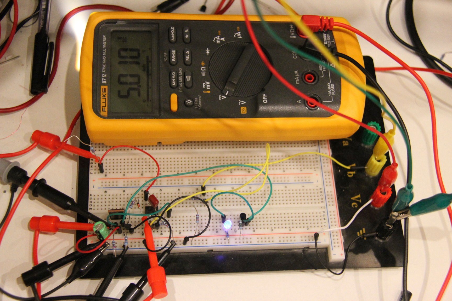
After fixing a high quality power supply (see here if you are interested) it spurred me on to have a go at designing and making my own – I think anyone who does electronics as a hobby will at some point or another build a power supply to use on their bench – I have not done that myself before so I thought I would give it a go. My aim is to use my basic understanding of analogue electronics and create a fully programmable bench PSU that will perform at least as well as the Agilent PSU, I think this aim is reasonable on the basis that todays components are considerably better than those that were available 20 years ago. Apart from the performance characteristics, there are a system engineering characteristics that I also want to consider because I would like to make it possible for anyone else to build this PSU as a DIY project with the ultimate aim of creating a high quality PSU that is modular and can be built in various configurations and be built at a hobby user or small lab price point. Here is a photo showing the very first working prototype regulating at 5.010 volts.
Why a PSU project, there are hundreds of them already? Firstly, the two areas of technology I really enjoy are electronics/embedded and software development and this project requires a fair amount of both to be brought together. Apart from that, no other reason than because I think I can do a decent job – we shall see 🙂
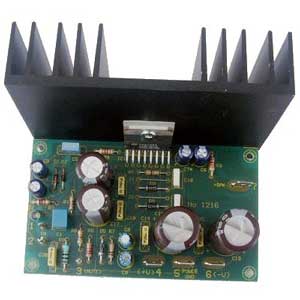
I thought it would be a good idea to try and set out what I have in mind. My aim is to create a modular PSU system designed to be used in lab or test automation environments. The first thing I want to create is a module similar in concept to those audio amplifier modules you can buy for building a HIFI amplifier, the module will physically look something like this.

The PSU module will take a single AC input from your line transformer of choice on its input and will provide a fully programmable lab quality Constant Current/Constant Voltage regulated DC output. The module its self will not have any kind of controls or display, but instead will have a fully isolated serial I/O which will be connected to a controller with the idea being you can create a multi-channel PSU with isolated outputs while also providing a single earth referenced controller that can be safely connected to a computer or other test equipment in test automation environments. Once I have created these modules, my intention will be to make a a few variants of controller, an RS232 interface and a PC software controller, a simple stand-alone control board with an LCD display and a couple of rotary encoders to control a single module and a more comprehensive control board that can control up to four modules with a nicer display (TFT/VFD?) and other interfaces such as RS232, USB and Ethernet to create a full function standalone multi output bench PSU.
Focusing back on the PSU module, I would like it to support a number of configurations with just a few component changes, primarily this is to allow different voltage/current ranges and resolutions to be selected to suit different requirements.
The headline specs for the regulator module are as follows: –
- Up to 50w of power
- Output range options 0-6vdc 0-5A, 0-10vdc 0-5A, 0-15vdc 0-2.5A, 0-25vdc 0-1A, 0-30vdc 0-1A
- Constant Voltage and Constant Current capable
- Remote sense capability
- Over voltage, over current, reverse power and short circuit protection at all power levels
- Optional on-board pre-regulator to lower the modules heat dissipation for higher voltage ranges
- On-board temperature monitoring
- Fully isolated serial interface for programming, control and monitoring
- Control resolution down to 1mV and 1mA in low voltage range
There are also some system engineering constraints I want to apply, these are: –
- Low component count
- Easy to source low cost components
- Easy to build DIY
- Physically robust construction
- One single PCB design for all voltage range configurations
In terms of my design approach, and I must state at this point that I am no analog electronics expert, I really just have a passing understanding. None the less, I want to avoid using the easy option in the form of the classic single package regulator IC’s that most DIY PSU builders use. LM317T, LT3080 and the like. These are great components, don’t get me wrong, but what you don’t get with these is a professional grade PSU without putting a significant amount of other electronics around them, by which time you have pretty much lost any advantage you have gained over using discrete components. Apart from that, one of the main drivers for this project is to learn more about building this kind of project and to share that learning with others.
In Part 2 I will describe my first attempt at building a discrete linear voltage regulator, with a schematic of the first working circuit along with a description of what I found along the way.
This content is published under the Attribution-Noncommercial-Share Alike 3.0 Unported license.
