I have been working on various power supply projects of late and was finding that my approach to loading PSU with simple incandescent laps was limiting. What I needed was a programmable DC load so I wondered – build or buy? Because I am already working on a PSU I decided that its probably better to buy one if I can find something that was reasonable quality and at a reasonable price. So I searched around and eventually took a chance on a Maynuo M9711 DC Electronic Load. I had not heard of the company before and could not find much out about them on on the internet, what I did see what that other similar devices that cost twice as much and had a reputable brand (BK Precision for example) were so similar in form that I thought its a good chance that they are different OEM’s of the same design. I am not sure that is the case because I do not have a BK Precision to compare, but I bought the M9711 brand new from the manufacturer on the basis that this was likely the case. Was I disappointed with the purchase? we shall see…
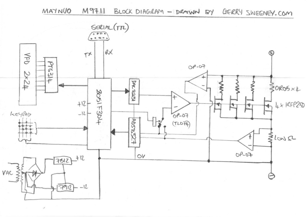
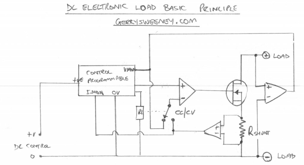
In this video I unbox and then tear down the Maynuo M9711 DC Electronic Load so we can take a look inside and see how it works and how well its been built. I try to explain how a DC electronic load works and I present a block diagram of the Maynuo M9711 based on my understanding and the cornerstone components that I find.
The main funcional components found in the device are:
| Part Numner | Description |
|---|---|
| Silicone Labs C8051F304 | This is an 8051 based 8-bit flash micro controller, this is the main processor for the device |
| Texas Instruments ADS8327 | This is a 16-bit SAR 500Khz Analog to Digital (ADC) voltage output converter, used to measure voltage and current in the load. |
| Texas Instruments DAC8831 | This is a 16-bit Digital to Analog (DAC) converter, used to generate the programmable reference voltage. |
| Princeton Technology Corp. PT6314 | This is a vacuum fluorescent display driver chip |
| International Rectifier IRFP250 | The power MOSFET (x4 in 150W model) used as the main active power device that creates the load load |
Notes and Diagrams
Below are the diagrams I present in the video describing the operation of a DC Load and the basic high-level layout of the M9711. You can browse these images or download a PDF document to print out if you prefer.
Well I hope you find this useful, thank you for reading and watching, catch you next time…

