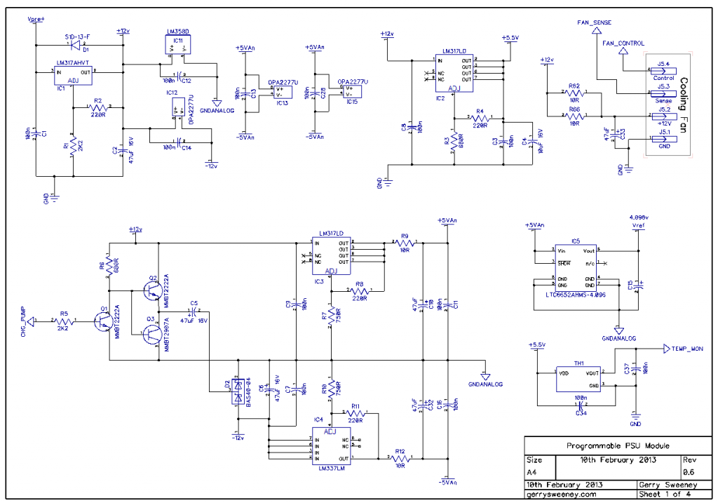
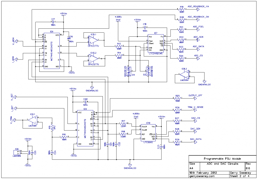
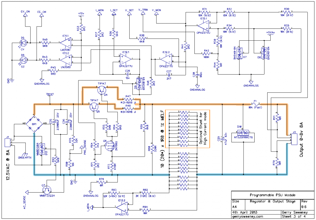
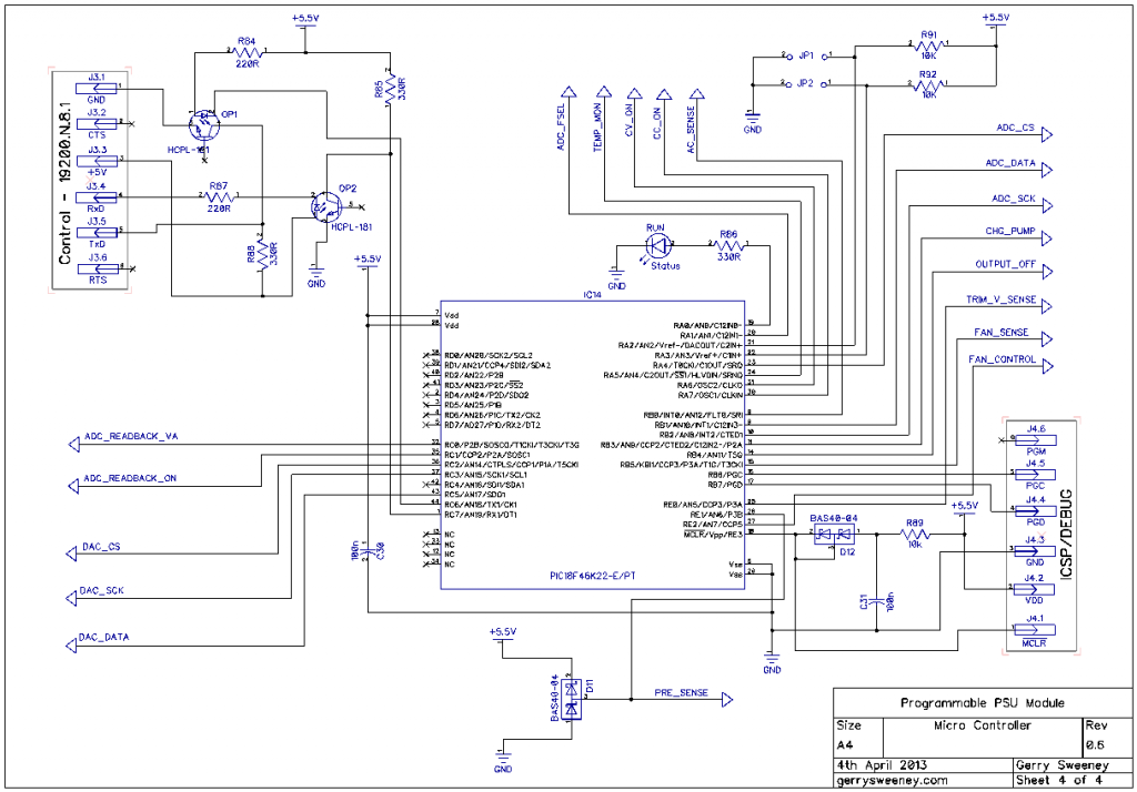
It’s taken me a while since the last update, I have been real busy of late. Having completed the first physical build, I now need to make various changes to the construction. Given the screw-up of the star earthing topology on the first board, I need to layout another board revision so I am going to make a bunch of other improvements. In this article I cover the various design changes and perform some basic power, DC condition and regulator response tests, I identify and resolve some issues and re-select better performing op-amps as an alternative to the LT1013, I have selected the OPA2277U part, and I have also tweaked the power supply implementation for the drive circuitry to reflect the fact that the newly specified op-amp is not a single-supply rated part.
The Schematic
Here are the latest schematic which is at version 0.6 including all of the latest changes.


I now need to test and resolve (or decide its acceptable) the overshoot problem when testing the load/no load dynamic response of regulator. I also need to re-layout the next board revision, get some boards made and build the next version. In Part 14 I am going to cover the firmware, describe the development environment and show the basic software layout as well as details on the current serial protocol I am using to control the module.
Thank you for your continued interest in this project, please give the video a thumbs up if you have found it interesting.