This is a follow-up to my previous article here. When testing the 1 PPS output I found some strange output which needed further investigation. I also decided to make further use of the microcontroller and status LED to indicate the 1 PPS signal to provide a degree of visual confidence that the frequency standard was working.
Various Pictures
The 1 PPS Channel
Here is the outline schematic of the digital channel of the video amp that is now used for the 1 PPS signal.
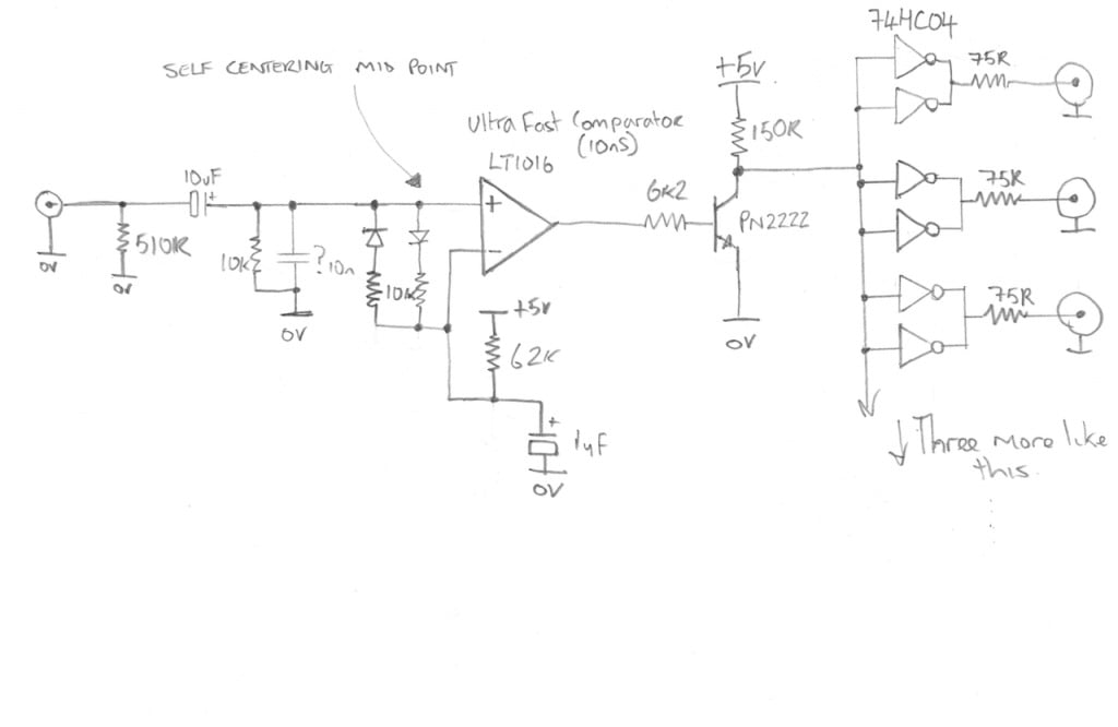
The fast comparator used in this circuit is an LT1016
The Micro-controller
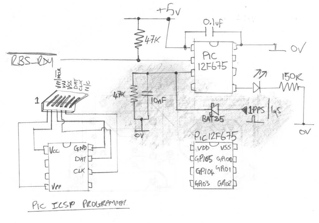
When I first tried to implement this I used (or tried to use) the edge trigger interrupt capability which on the face of it should have been the perfect solution. However, no matter what I tried I could not get it to work, the best I managed to achieve was getting it to work some of the time, but it was very random. I suspect this was down to the way in which the PIC12X handles interrupts and context state saving implemented by the compiler, I read somewhere on the microchip forums that this issue *could* be resolved by upgrading to the PRO version of the compiler…..hmmmmmmm. Anyway, I decided to change tact and poll for the 1PPS signal which meant I also had to construct a really simple pulse stretcher circuit to ensure I was able to catch each pulse. Not as elegant as an interrupt-driven solution but it works. I think the more advanced PIC18Fxxx series micro controllers would have worked using interrupts but those are big chips and I was already committed to the PIC12F675.
Here is the schematic for the micro controller which now also monitors the 1 PPS output of the RBS. The shaded area is what has been added to the circuit since the previous article.
Here is the firmware source code with the 1PPS implementation added. Its implemented as a simple state machine in run mode, I have tried to keep the code simple to read.
And for those of you that just want to program the chip, here is the compiled HEX file.
Catch you next time….
This content is published under the Attribution-Noncommercial-Share Alike 3.0 Unported license.
Hi Gerry
All 10MHz RS videos are fantastic!
1. Very professional
2. Clear and easy to understand
3. Good examples
4. Very nice on going problem solving
And so on . . .
I learned a lot !
Keep on the good work!
Dror
Hi Dror,
Thanks for the feedback, I am glad you like the videos
Gerry
Hello Gerry, on the off-chance that a dozen other people don’t mention it (!) Your non-contact IR temperature meter will ASSUME that it is looking at a less reflective surface than your shiney aluminium front panel. It will woefully under-read the actual thermal temperature, as a result. Google Emissivity Coefficients (if you really must!) OR – just stick a bit of insulating tape on the metal front panel, and point your IR meter at that, instead. I’ll guess at 45 degrees.
PIC overkill? Nah! I think you should use the spare GPIO ports on that PIC to drive a small LED matrix array back-and-forth, a-la “Night Rider”
Hi Laurence,
Someone else did point this point this out to me, I ended up using black tape as you suggest and it was reading about 36 degrees C instead of the 29 I measured in the video. I should have cross-checked with a thermocouple really 🙂 Thanks for the pointer.
Night-rider light, hmmm, maybe, always wanted to find a need to make one of those…. 🙂
Gerry
Thanks for posting your projects, they are really informative and well done.
John
Hi John,
You are welcome, thank you for you feedback
Gerry
Heck of a job there, it abulestoly helps me out.
newbie question… what’s the intended purpose of the 1pps signal? Can you elaborate on how you plan to make use of this added signal? I must be missing something here…perhaps it’s a radio-enthusiast type of utilization or ?
You can use it to drive a clock 🙂 Some gear can synchronise to a 1 pps signal where you have a slow loop time. Imagine feeding a counter with a frequency thats resent and held once a second, thats a basic frequency counter. Gerry
Gerry,
I noted that in your schematic, the signal from the Rubidium Standard indicating “locked” is called “RBS_RDY” (with a “B”), but in your code it’s being called both “RFS_RDY” (in comments), and “RFS_READY” (in code). I’m presuming the first two of these are typos and all refer to the same signal going into GPIO5.
Hi Chuck, yes thats just a typo I probably changed my mind on the name – I tend to do that a lot 🙂 Gerry
Ordered from E-bay today the case Extron ADA 4 300MX HV for the Rb ;distribution project. Less outputs, but same size case (and less $$.$$) Some cases have one less row, so do not have the side spacer that you drilled the vent holes in. And those smaller cases (with different electronics) may not work with your Rb project. Do not have the Rb, GPSDO or a OCXO for the project yet. A question on the 1PPS; the output is 75 olms and not the 50 olms like the 10 MHz ? And any easy way of the 1PPS to trigger a clock ? Keep up the good work, tjl
Hi Timothy,
You should be able to trigger a clock from the 1pps output but the rise time is very fast and the pulse is only 1uS wide so keep that in mind. In my project I had to stretch the pules to get it to reliably clock the PIC chip.
Gerry
Hi,
Could you please specify the model of the three mini power supplies used here?
Thanks,
Milos
Hi,
The model of the PSU is a TDK-Lambda LS35-15
Gerry
Hi Gerry, I wonder if you still have the dead Rb standard ?
They have a multitude of options and I’m having a little difficulty understanding them, from the block diagrams I see, the DDS chip inside is used to generate a modulating signal for the Rb lamp drive and not the output frequency. I’m wondering if the unit you had has a second DDS or if the 10MHz signal was derived directly from the 60MHz reference by division?
Hi Clint,
I believe the 10Mhz is derrived from a DDS chip directly, I am not 100% sure of the various configurations myself to be honest, its all very confusing.
Gerry
Really Really Really want one of these devices…how can i go about obtaining one from you?How much is it?i want to connect is to my Antelope Isochrone OCX Word Clock…Let me know ASAP
HI Germaine,
I am not sure I understand the question, what are you looking for? A video distribution amp for master clock distribution?
Gerry
Gerry, here it is 2017 and I found your information & video. Building on for myself. Will use old server case ( 4u ) and install 2 different 10mhz sign wave signals. One from efratom rubidium source and the other from GPSDO with high gain antenna. They will be used side by side for comparison to start with. Will send signals to oscillatoscope, spectrum analyzer and hf radio for timing. It’s hard to believe that you made this so simple and cheap, even I can afford this project. Thank you and keep up the great work . I hope to see more of you and your videos in the future !
Hi, also curious about the “dead!” Rb: seems that bad tantalums can be repaired.
I had this problem on my SDR and a multimeter but fixed it before anything got cooked.