Having gotten myself a Rubidium Frequency Standard I found that the unit on its own is not that useful, its really just a component and needs really a supporting PSU and a decent enclosure to make it useful. I was searching around for something suitable when I was directed to a robust quality unit being sold on e-bay for just £20 with an unbelievable level of re-usable content and turned out to be an almost perfect solution to making the Rubidium Standard a useful Lab item. Rarely does such a fine marriage of junk bits come together to make something really useful?
I had a lot to cover, the whole thing was built in an afternoon and as a result, this is a long video at 1 hour 16 mins so be prepared…
The PIC Micro-controller – PIC12F675
The original plan was to use the PIC for three functions, the first was to make the power LED flash while the RFS was warming up and on solid when locked. The second was to generate a 1 PPS signal from the 10Mhz signal and the third was to generate a PWM signal to control the fan speed. As it turns out the RFS already has a 1 PPS output on Pin 6 of the DB9 connector so there was no need for this. It also transpired that the only fan I had to hand was a three wire fixed speed fan, so I also did not need the PWM signal, this left me with just the power LED to deal with which is what the PIC ended up controlling. Here is the schematic for the PIC and the source code.
And the compiled HEX file if you want to just program the chip without compiling
The Video Amp – Extron ADA 6 300MX HV
The video amp unit I used in this hack is made by Extron and the model number (on the front panel) is ADA 6 300MX HV. When I communicated with the seller, he said he had about 30 of them, so if this is useful to you and you want to make your own I would go grab yourself one before they are gone. The basic outline schematic for an input channel is here:
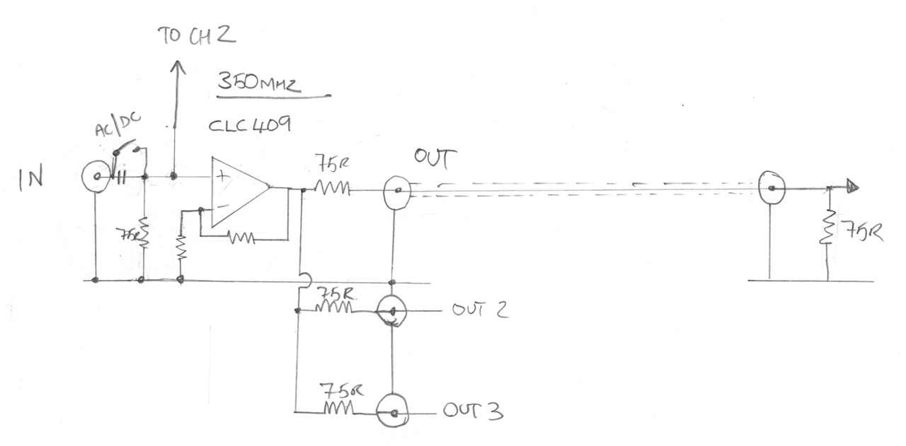
The video op amp chip used in this unit is a CLC409, the Texas Instruments CLC409 Data Sheet data sheet is attached to this article.
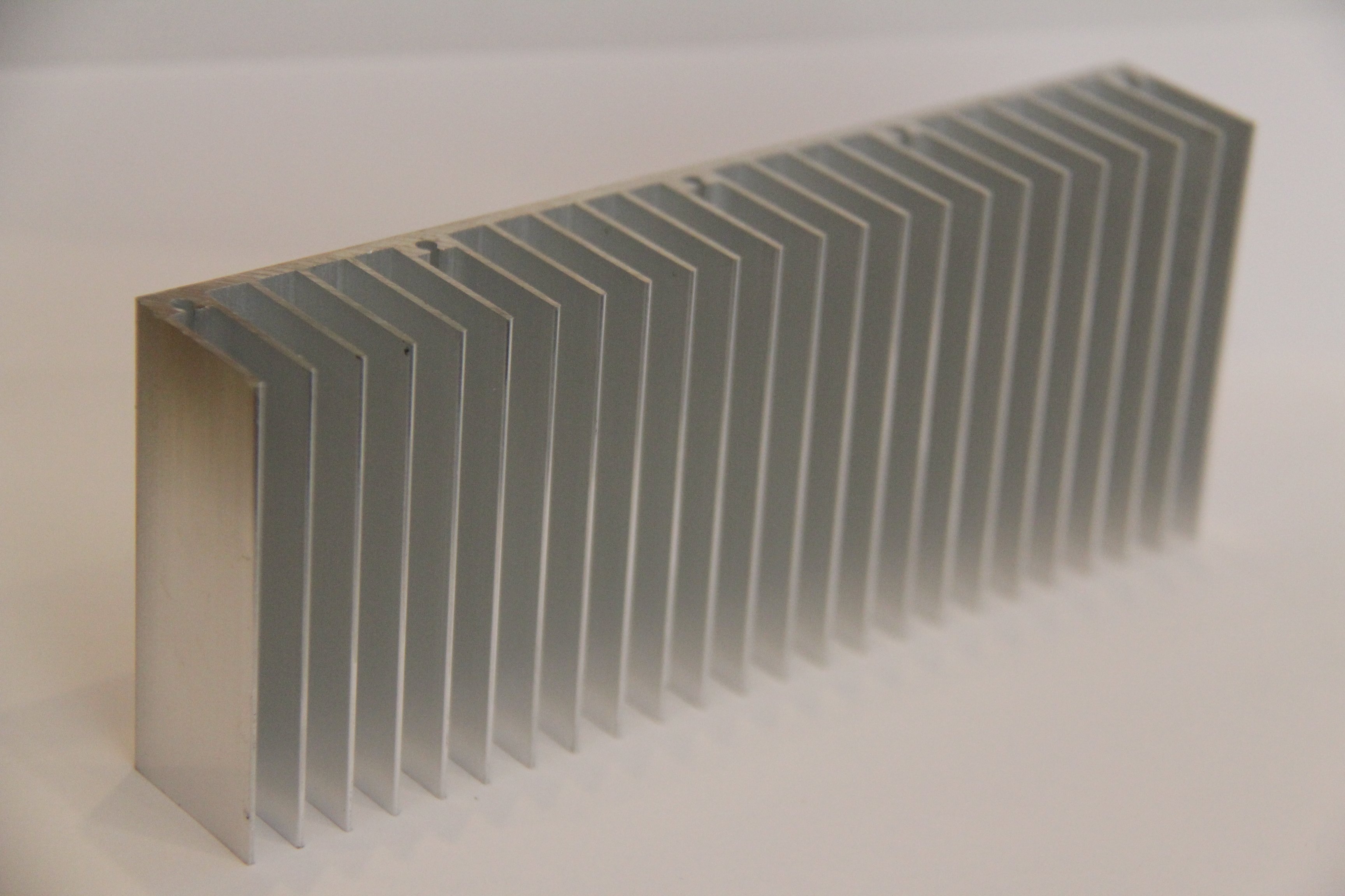
The heat sink I have ordered can be found on e-bay, search for “150x25x60mm Aluminum Heat Sink for LED”.
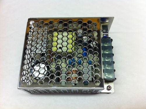
The switch mode PSU I used can also be found on e-bay, search for “Enclosed Power Supply SMPS,15V,2.4A,36W, it is made by TDK-Lambda and the part number is LS35-15”
See you next time.
This content is published under the Attribution-Noncommercial-Share Alike 3.0 Unported license.
Attachments
| File | Description | File size | Downloads |
|---|---|---|---|
 Texas Instruments CLC409 Data Sheet
|
418 KB | 4498 |
Hello Gerry,
That was a very satisfying build! what a great case – the project came together almost with Heathkit (Remember them??) or Mecano-like precision. I like it.
May I offer a couple of suggestions?
Your Fluke meter has a “hold” mode, which will wait for a stable reading, then lock it on the display with a short confirming bleep. This allows you to keep your eyes and all attention focused on positioning the probes, until you get a bleep. Then you back off, and turn your gaze to the meter. Otherwise, there’s the ever-present chance of a slipped probe, shorted output and unhappy lump of silicon… (yes! I’ve done it myself).
I reckon those Rubidium boxes LIKE to run hot! I’ve put mine into a smaller metal box, but I notice that if I applied EXTRA heat sinking, it merely draws MORE current, as it attempts to heat up my entire lab… So I DON’T think you need that front heatsink.
I loved the use of the tiny PIC! A good demonstration of the idea. I just wired a Red/Green LED and some simple push/pull logic to my “locked” signal, so that the LED is always on (so you can see the power is OK), but Red for not locked, green for locked and ready. Always many ways of skinning the cat.
I’ll bet the remainder of those video distribution amplifiers will now sell quickly! I’d have followed your example myself, but I’ve already squeezed mine into a small Hammond case.
Yes – a nice satisfying project with a real end product. Can’t see you running out of buffered 10MHz reference signals, any time soon…
Laurence
Hi Lawrence,
It is definitely rare that to hack a bunch of thing so nicely together. I cannot take credit for the find of the video amp though. Someone that watched the previous article put me onto it, I had to buy a couple once i saw them. Cheap and really idea for this project. Yes, I should probably use the hold feature of the meter, I am a bot lazy and I have blown silicone too….:)
Gerry
Thanks Gerry. Great video! Fine little project.
BR Jonas
Thanks for the comment/feedback Jonas.
Gerry,
The DC mode on the amp will almost certainly be to try and maintain the ‘black level’ on the video signal.
Span, yep that would make sense. Not sure it matters too much for my application though. Gerry
Nice find, great build. Being a lab equipment, I would also put a bnc jack on the front panel, though.
Hi Cristiano,
I will see how things pan out when I mount the heat sink on the front panel. Thanks for the suggestion, its a nice idea.
Gerry
Hi Gerry,
1 The design is unique. I think that you have more of these video splitters ? why ? Others also want to do this myself so I have to buy it.
2 PIC for a flashing LED? Crazy
3 The fan outlet is, OK. But where’s intake of breath? Again ZONK 🙂
Generally the whole idea OK (well, almost) but for viewers in general not useful.
Marcin
Hi Marcin,
1. Yes I bought two of them, I have a Thunderbolt GPSDO which also needs a nice enclosure and generates a precision 10Mhz reference.
2. Yes perhaps, but cheap and easy…and I had them to hand. The code was no more complicated than a 2 minute hack…easy too.
3. The intake is underneath, cutout of the bottom of the unit. The case has rubber feet which raise it about 9mm from the surface, plenty of room for a slow air inlet.
Gerry
A very cool hack! I’ve been thinking of getting a rubidium standard for some time, but the thought of using a video distribution amp had never crossed my mind. Pure Genius! I’ll have to add this to the project list 🙂
Glad you like it, thanks for the feedback.
Gerry
Hi Gerry,
First, you did a nice job on the project, However ……
Apparently you did not read the manual for that Rubidium unit. It is available on the web but I will send a copy via email.
Yes they run hot, but they are designed that way AND DEFINITELY NEED A HEAT SINK. The physics package inside needs a certain temperature to cause the otherwise liquid Rubidium metal to go to the gaseous state. The electronics inside is unfortunately stressed by the heat, so to help that part you need the heat sink. The bottom plate of the Rubidium is the heat transfer surface and should be around 45 to 50 degrees C maximum. The nominal current draw at that point will be around 800ma. If you let the unit run hotter (i.e., lower current draw) it will eventually just fail due to excessive heat buildup inside the Rubidium. Because of this you should make sure you remove the paint from the reversed front panel. And use a lite coating of heat sink grease to ensure good heat conduction between the Rubidium to front panel on the one side and also on the other side for the heat sink.
The metal container of the Rubidium is made of MU-metal for magnetic shielding. Excessive heat could cause the MU-metal function to reverse itself (also a problem when drilling holes in it) and become ineffective over a long time, not to mention increased failure of the integrated circuits inside.
Finally, while it is an “Atomic” standard, it is not perfect, that is to say the Rubidium may not really be “spot” on (to borrow a phrase from that guy on EEblog). One of the two I have is off by 2e-10. The unit can be adjusted to be very close to “spot” on. Also, the Rubidium will drift, albeit at a very slow but observable amount, about 1e-11 per month. Its short term (less than 10 seconds) stability is not as good as a very high quality oven Quartz oscillator, although its long term stability (months) is better than Quartz (days).
Starting down the path of having a frequency standard is a very deep hole from which you will never climb out of (just a word of caution). Your next step is to have a “Timing” GPS setup to watch (and perhaps correct) the drift on the Rubidium. A special GPS set up for timing (relatively inexpensive but more then the cost of the Rubidium) is quite noisy in the short term but is virtually a constant in the long term (years) because it is a direct derivative of a Ceasium frequency reference.
Don’t forget to fix the front panel
73….Bill….WB6BNQ
Hi Bill,
Thanks for the detailed information. I have to say I did not read the technical manual for these units, but my instinct was definitely to cool them. In fact, having tested my build now I am back I found the front panel alone seems to be sufficient to keep the temperature of the unit down to reasonable levels, but I am going to fit a heat and I was planning to use heat sink compound on both sides of the front panel. I will also check the heat transfer properties of the font panel and adjust if needed.
I was aware that they drift a bit over time, I think thats over continuous use, I plan to only use mine when I need it. Also I have just bought a Trimble Thunderbolt GPSDO and I have a second Extron video amp so you can work out what my next frequency standard related project is likely to be 🙂
Again, thanks for the info and the advice and the manuals, very helpful.
Gerry
Hi Gerry,
Neat mod and video!
Out of curiosity, how warm is the case in general and the panel with the Rb behind it?
Angus.
Hi Angus,
After about 3 hours running, the front panel is warm to touch but is no where near as hot as a cup of tea. The case is mostly cold due to the light air flow.
Thanks for the feedback.
Gerry
Hi Gerry. Nice build, looks really professional. Can I ask, where did you get the BNC blankers? I can’t find them anywhere.
Hi, to be honest I have no idea, someone gave them to me. I will ask and find out and post back on here. Gerry
Gerry – those blankers are from here
http://uk.farnell.com/jsp/search/productdetail.jsp?SKU=1269047
Hi Andy,
ah thats great, thank you for posting.
Gerry
Thanks, appreciated.
Hi Gerry – came here from EEVBLOG & hackaday – like the videos – keep ’em coming !
Thanks for watching. Gerry
I just found your site the other day. The Rb standard is a really excellent series. I’m just setting up a small home lab and have been thinking about a good frequency standard. It looks like your series should help solve that problem.
I have attached a web site that I ran across today that you may have seen. More info on DIY Rb references. I’m sending it along anyway in case you haven’t.
http://www.vk3um.com/Rubidium%20Standard.html
Keep up the excellent work. Your stuff is really useful.
Bob
Hi Bob,
Thanks for the feedback, I am glad you found the post useful. When I first tested the RbFS I made a post and included a bunch of useful links, the one you mention is already there. Have a look at this page there might be other useful information that you are not aware of: http://gerrysweeney.com/i-need-10mhz-how-hard-can-it-be/
Gerry
Hi Gerry,
i came across your videos while searching for the FE-5680A rubidium frequency standard. I want to build my own reference with a signal distribution system similar to what you did. One thing i can’t find anywhere is how the fe5680a powers up with a current limit. Since the supply current goes down relatively quick in the first seconds after power is applied i was wondering if i could use a 1.5A or even 1A power supply and limit the current to the device not to overload the supply. Since the steady state power consumption is much lower than 1.7-2.4A i would like to avoid using a 3A power supply or something similar just for the first few seconds. Did you by any chance try something like this? I can’t test it myself since i don’t have a fe5680a yet, the prices have gone up quite a bit since you built your reference.
Keep up the great work!
Hi Daniel,
I did not try that to be honest, I would imagine it would work, the bulk of the current is drawn by a couple of TO220 Fets welded to the casing of the physics package so to that end its simply a current sink using the heat to get up to temperature. The only thing I am not sure is during current limit the voltage will be lowered and I am not sure if that will have an effect on the rest of the electronics, you would need to try it. That being said, with switchmodes being so small, why not use one rated for the job, once warmed up the switchmode will only draw the power needed and no more, they are small and efficient in that regard. Good luck with the build…
Gerry
Thank you for the fast response!
I initially thought about limiting the current because the LS25-15 is only about 40% of the size(volume) of the LS35-15 and it would fit better into the case i thought about using. It’s maximum current is 1.7A(limited at 110% of that). It looked like the current went below 1.8A within 1s and below 1.7A within 5s…Then i started looking for different methods to limit the supply current.
I agree with you, it’s probably best just to buy the correct power supply and be done with it. But i get lost in this kind of stuff and research about it 😉
Do you still have the not-locking fe5680? I would be glad to tear it down to see if the 15V input is only used for heating and would not suffer from a reduced input voltage for a few seconds.
Hi Daniel
I do have the one that does not lock but I gave it in the list if my teardows to do I sm afraid
Gerry
No worries, i am already looking forward to your teardown!
Gerry, thanks for the You Tube videos on the Rubidium 10 MHz frequency standard and Video Distribution case. I used your videos to house my FE5860A and everything worked out nicely. I did move one of the 10 MHz outputs to the front panel. Now I need to make a housing for my Thunderbolt GPSDO so that I can compare the two frequencies. Your video solved several problems for me. I can send a picture of the finished product if you are interested. Your videos are well done.
Hi James,
Thanks for the note, I am glad the video helped you. I too have a Thunderbolt GPSDO project to undertake at some point. Yes I would love to see a picture
Gerry
Great job, I have found my next project.
Awesome, thanks for the feedback, good luck with the project. Gerry
Hi Gerry. Very interesting video.
Just a thought, you’ll probably find that the PCB microstrip and the BNC connectors are also 75 ohm. I’ve got a FE-5680B which doesn’t have 10MHz sine but does have 20MHz square; I’m expecting to divide by 2 with a D-type flip flop. Do you know if test equipment has a preference for wave shape? Cheers
Hi Andre,
In practice most test equipment seems to lock to anything that resembles a square wave or sine wave. However, from a pure design point of view a pure sine wave is always going to be better as the harmonic content will be significantly less, the lower the harmonic content the lower the chance that the equipment using the signal will accidentally lock onto a harmonic rather than the fundamental. If i was coming from a square wave I would probably try to feed through a second or third order notch (or low-pass) filter to try and kill of as much of the harmonic content above and below the fundamental as possible. Never dried to design such a filter, but something close to a 10.7Mh IF filter in an analog radio circuit (tuneable tank and some gain) or even a 10Mhz xtal filter would probably do a pretty decent job I would have thought. Another option would be a clean analog oscillator phase locked to the square wave out of your RBs. I have been thinking about using an OCXO frequency locked to the RB’s to solve one of the other problems these frequency standards exhibit – but thats a whole new video 🙂
Gerry
Hi Gerry
You may be interested in another Rubidium offering. I got the idea for the case from your video so it only seemed fair to credit you in the writeup. In the end I settled for a square wave as it was easier.
Many thanks
Andre
http://andrelubbock.blogspot.co.nz/2015/09/rubidium-frequency-standard.html
Hi Andre,
Thanks for the link, nice work and great write up. Thank you for the mention, I appreciate it.
Gerry
Gerry,
I don’t really know how much experience you have with frequency standards. But I like to mention that Rb Clocks, as well as Cs and ovenized Quartz oscillators, are precise frequency standards. The quality of DC power is very important, you can not slap a switching power supply to it and expect the thing to work within specs. Same goes with vibration and temperature environment, they are NO-NOs. Great care is required.
Also, the distribution amplifier that you use to drive several measurement equipment, has to be of the same quality level or better than your frequency source. The figure of merit that all experts use are “phase noise” and “Allen variance”. Goggle them. Or even better visit the web sites of the premier metrology labs: NIST, NPL, PTB, etc. There is a reason why the number of companies manufacturing frequency standards are limited. Too many small details to watch.
I expect that the instruments connected to your Rb frequency will perform worst than running from their internal frequency reference.
You have in your hands a very good Rubidium frequency source. But to get the best performance out of it, the rest of the electronics has to be up to par.
Regards,
Ernst
Hi Ernst,
Thanks for the comments. Yes I have read that the PSU for the Rb standard is important but from the best I could tell in my home lab it really did not make a difference. Now thats a big statement to make I know and I am sure that a better quality linear PSU would be both academically better and possibly lower the noise on the sine output but for my use at least I don’t think I would gain anything – I imagine all the time nuts will be wanting to dispute that of course. Actually what I have found is the Rb is not that great a frequency standard for lab use because it uses a DDS to generate the 10Mhz signal and the DDS skips cycles sometimes because of the way DDS works, so the Rb while having excellent long-term stability actually does not work well for lab standard calibrations, it can be a bit jumpy. The phase noise introduced by the DDS chip is far worse than any PSU noise (within reason) could create – I plan to do a video showing exactly this. Now that being said, if you ignore the jumps in frequency you get every now and then from the Rb time to time, I can run the Rb and an OCXO together and measure only 3 to 5 100ths of 1 cycle deviation and that is entirely repeatable month in and month out. Regardless of anything else, the fact that I can run two totally independent free-running oscillators and they can stay in step with each other to that degree is remarkable and certainly is good enough for what I use it for.
It seems to me the best configuration is likely to be a high quality OCXO with sine output, frequency locked (not phased locked) to the Rb, that would give you the short term stability of the OCXO coupled with the long term stability of the Rb, and thats something on my list of things to do as an upgrade to my distribution amp/Rb project.
On the point about the distribution amp, in my case at least I am not sure I agree. My observation is neither the OCXO’s or the Rb’s that I have played with output a spectrally clean sine wave, they both exhibit some degree of harmonic distortion so the quality of the sine wave through the distribution amp is no worse than what comes out of either device directly. In practice, the lab gear only uses and external 10Mhz reference to frequency lock their internal oscillators sync digital circuitry (in the case of a frequency counter or signal generator) so as long as the sine wave is good enough to sync to then apart from a minimal phase shift it might introduce, it will have zero effect on the accuracy of the frequency component.
Thats my understanding anyway.
Gerry
Hi! Just want to thank you for your excellent videos. I used a modified version of your upgrade of your Racal-Dana frequency counter for an old Fluke counter using the same OCXO you used. So I now have a counter made in 1987 running spot-on when measuring against my Trimble GPSDO. And naturally I found this video just when I run out of 1 PPS and 10 Mhz outputs. So I ordered a unit and follow your instructions. So thanks again for making a not too rich guy getting access to precise equipment without breaking the bank.
Regards,
Jack Zimmermann
PS: Keep those videos coming! 🙂
Hi Jack,
Thanks for the feedback, I am glad you like the vids and they have helped you out.
Gerry
Hi Gerry, very nice project indeed. It got me the Rubidium bug. I am wondering if you ever also gave consideration to the Symmetricom SA22C unit? It seems now a days that all of the FE-5680A’s that are being offered on Ebay are in China, not that would be a bad thing outright, but I would feel more comfortable dealing with a seller in North America. There is actually one seller In the US that offers the SA22C, and at a lower price than any of the chinese 5680’s which BTW seem to have gone up in price since the Rubidium craze started a few years back and has increased demand for them. Anyhow, the SA22C looks quite alright to me, but since it has the interface connector located on the same face of the mounting surface that needs to be attached to the heatsink, its a bit more challenging to mount & connect. Just wondering if you (or anyone reading this) might have any thoughts on this unit being suitable (or not) to build a home lab standard. Here is a link to the SA22C manual: http://www.rdrelectronics.com/skip/feb/SA22c.pdf
Thanks.
Alex
Hi Alex,
I have not played with one of these but I would say it looks more than suitable to build a home lab reference with.
Gerry
So I thought I would share this for others looking to follow you down the rabbit hole as it were. For the Extron ADA 6 300MX the resistors determining the termination resistance are 75 Ohms as you note. But test equipment and most radio gear as well expects 50 Ohms requiring a bit of rework. My solution was simple. I bought a roll of 1206 surface mount resistors at 150 Ohms. These are the same size as those on the board of the unit I picked up on Ebay new. I simply stacked one on each of the existing 75 Ohm resistors. The result is elegant and simple to do and results in the desired 50 Ohms impedance at the BNC connector. Only issue now is what to do with the other 4,982 resistors I have left over… Though I don’t think I will be doing the PIC circuit portion of the build I will be implementing most of the great idea in my own way. Thanks for very detailed info and the great site Garry!
Hi Michael,
Thanks for the feedback, good simple alternative to replacing the resistors, end goal achieved 🙂 thanks for the sub to my blog.
Gerry
Thanks Gerry for sharing your project. I picked up a similar video amp cheap on eBay and followed your example to many outputs (10mhz and pps). It turned my rubidium standard into a real bit of kit instead of just a novelty. I picked up a second video amp (price was right) and am investigating GPSDO boards and plan to build a similar project using a scrap OCXO board. Thanks again for the inspiration and all of the details.
Your welcome, glad you found it of some use
Gerry