As part of the process of upgrading my counter to have a DIY high stability OCXO (Oven Controlled Crystal Oscillator), someone who watched my videos had designed a DIY 3GHz Channel 3 53131A-030 option board. The original from Agilent is very expensive (obviously) and there are clones you can get on e-bay which are a quarter of the price Agilent charge which is why he decided to design his own. His name is Andy and when he saw my video’s he got in touch and offered me one of the PCB’s to which I of course said YES PLEASE 🙂
Now as it turned out, when Andy constructed his own board he had enough components left over so also constructed and tested one for me which was a really kind thing to do and very unexpected too. In exchange for this I have insisted that I can build him an OCXO board while I am doing mine to return the favour.
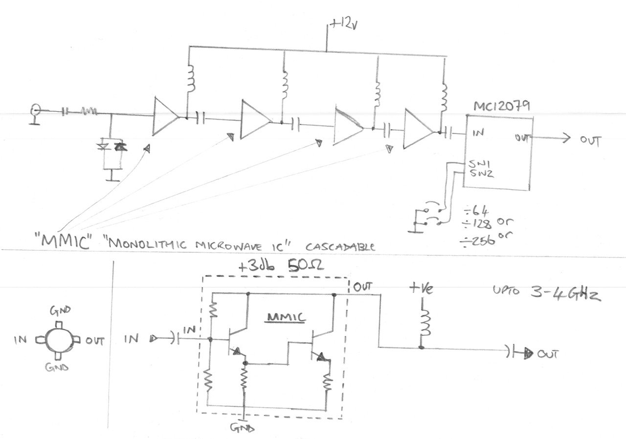
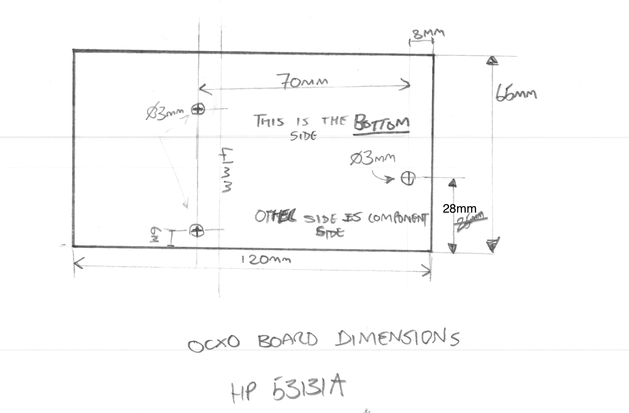
Anyways, I thought I would do a video to show the HP/Agilent 53131A-030 DIY 3GHz Cannel 3 Option board getting fitted to my counter. I also spend some time explaining how the pre-scaller circuit works and in basic terms what MMIC’s are and how they work too. I also make an adaption to my previous hard power switch modification to make way for the upcoming DIY OCXO board, and I measure up to get the exact board dimensions and mounting hole positions I need for the OCXO PCB layout.
The entire work and full attribution for the DIY 030 option board/PCB goes to Andy, so Andy – thank you so much for making one of these for me – I really appreciate it.
PLEASE NOTE: I will not put Andy’s Youtube/EEVblog ID here unless he asks me to, and I will not pass on his details without his express permission so please don’t ask – I respect people’s privacy. If Andy does want to share his details in connection with this project then I will gladly put them here.
PLEASE ALSO NOTE: The schematic drawing below is technically incomplete and is meant as an illustrative block diagram. In the real circuit there is also a resistor in series with each inductor at the top of each MMIC to set up the right DC conditions.
See you next time.
This content is published under the Attribution-Noncommercial-Share Alike 3.0 Unported license.
Thanks Gerry.
The mmic gain is actually set with a resistor in the supply line. ( in this case the 180 ohm resistor ). This sets the supply current to about 35mA. Which for this mmic ( MSA-0486 ) sets the gain somewhere between 6-8dB.
Andy, of course, that makes perfect sense. Thanks for the clarification. Gerry
Thinking about that a little, I guess though this is only settable within limits which are broadly defined by the internal resistance of the emitter resistors and bias range.
Gerry
Yes – for this device the datasheet suggests between 30mA and 70mA.
According to the datasheet the current should be ( for 12V supply and 180ohm bias resistor )
(12.0-5.25)/180 = 37.5mA (5.25V is Vd in the datasheet )
And my PSU showed around 200mA for the board in testing.
4×37.5= 150mA
The MC12079 is typically 9mA
The 5v6 zener supply should draw about (12-5.6)/180=35.5mA
Total gives 194.5mA – pretty close to the measured value.
Hi Andy, yes you are of course right, the gain would be set by the DC current. The values make perfect sense. Gerry
Just some more comments about why the expensive HSMS-8202 diodes are used instead of say a standard and cheap 1N914.
The capacitance acoss the junction of a 1N914 is 4pF , and the HSMS-8202 is 0.2pF
There are actually 4 of these diodes in parallel across the input which gives figures of 16pF and 0.8pF , calculating the 3dB point for a 50 ohm input gves us around 200Mhz if we use the 1N914 and 4Ghz if we use the HSMS-8202.
Hi Andy,
Yes of course, I remember you saying this now, that makes perfect sense. They are not the cheapest things in the world at about £1 each!
Gerry
There seem to be various 3rd-party upgrades for these counters now, both to add the ocxo and enable channel 3. Some are on ebay, some are blogs, some are pcbs etc.
Can anyone recommend where to get a channel 3 board ? 3GHz would be fine, 5GHz would be fantastic. Some of the articles describe the problems of stopping self-oscillation – I’ve encountered that on a similar mod I did to a Philips PM6666 and would prefer to avoid it if possible.
I’d rather buy a well-thought-out mod like Gerry’s than an unnamed ebay ripoff.
I also need to replace some fans but am unsure of the best speed to use. Suggestions welcome.
Hi Adrian,
I bought one of these: http://www.ebay.co.uk/itm/3GHz-Prescaler-for-HP-Agilent-53131A-53132A-53181A-Counters-/111498681063?pt=LH_DefaultDomain_0&hash=item19f5d6dae7 but have not yet tried it, in fact I have lost the bloody thing, buried beneath the pile of other things I have to get to one day!
Gerry
Hello Gerry,
I would buy this PCB only (HP/Agilent 53131A-030 3GHz Channel 3 Option Board). Can I pay through PayPal. Do you offer this card for international sale? How should I proceed? Where to buy?
Thank you,
Julio Cesar M. da Costa
Brazil
Hi Julio,
I am afraid I don’t have any of the 3Ghz Channel 3 PCB’s, I never got around to making any more.
Gerry
Hello Gerry,
I want to buy only the PCB without components, because I already have the components and just need the PCB.
Thank you,
Julio Cesar
Hi Julio,
I do not have PCB’s for the 3Ghz option board I am afraid. I only have bare PCB’s for the OCXO option board.
Gerry