Now I have the requirements for the control ranges I need its time to get down to the nitty-gritty and get a DAC up and running so we can make some measurements. The maximum dynamic range I need for this project is 6000 individual steps – this was identified in the calculations for the voltage control for the 0-6V rage in Part 5, so let us start there.
There are many options for DAC’s to choose from, I want to keep the cost and component count down so my starting point is a low-cost single component solution from Microchip, part number MCP4822. This is a dual 12-bit DAC with two channels and a built-in voltage reference. I get independent voltage and current control from one 8-pin chip – wow! However, there is a problem with this part, it only has 12-bit resolution which will only give me 4096 individual steps and my design calls for 6000. The problem with choosing components with a higher number of bits is that they start to get expensive. I want to see if it’s possible to extend the range of the DAC using software and a technique called “dithering” or “modulation”.
The idea here is pretty simple, to increase the resolution of the DAC you can continuously switch the output between two or more codes, feed the result into a low-pass filter and get the average voltage. If you switch between two adjacent codes with a variable mark space ratio like you do in PWM, it should be possible to extend the range of the DAC without creating large ripples on the voltage head making the low pass filter easy to construct. That is the theory at least, I need to try it and see what the results are in practice.
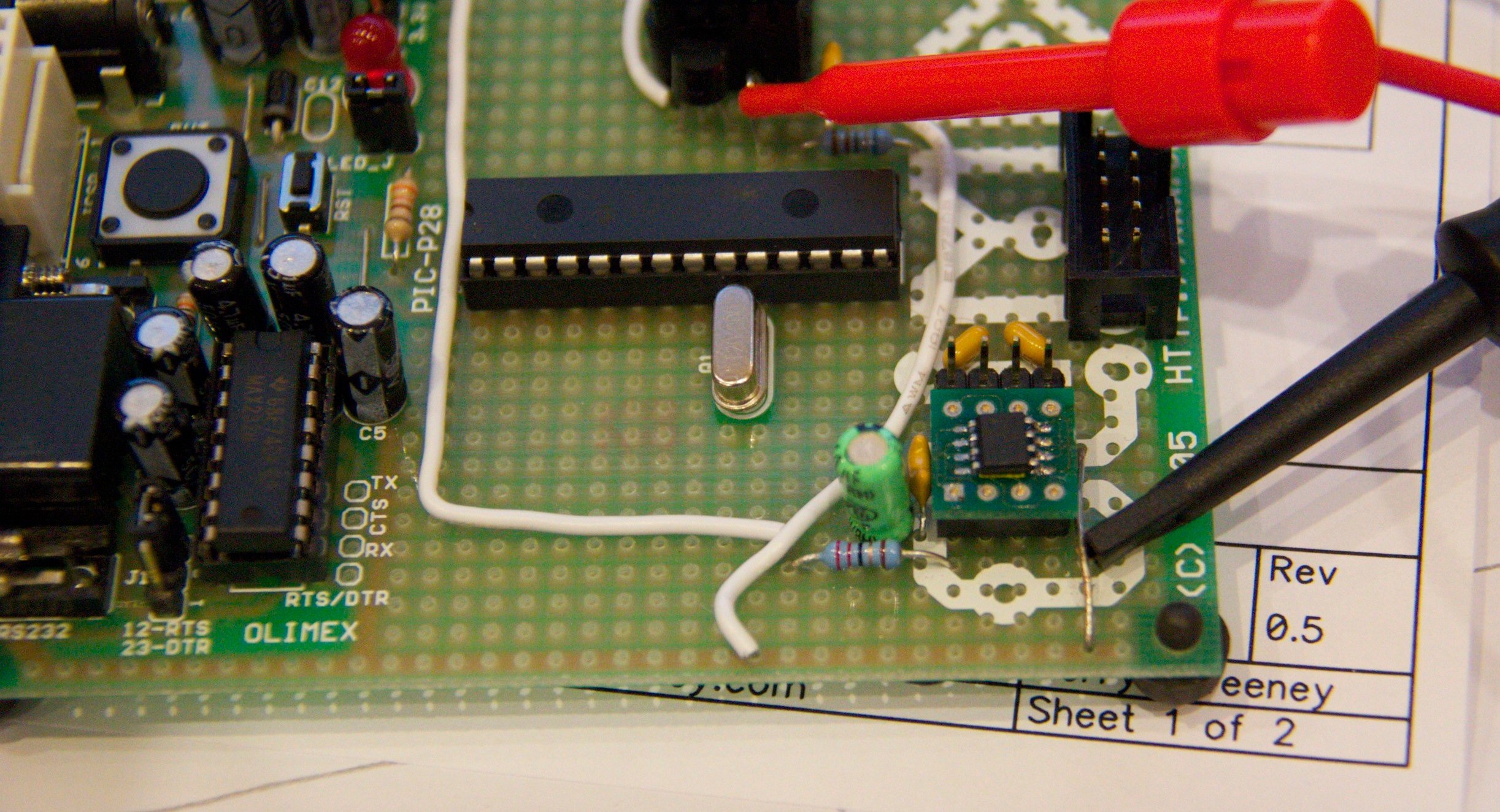
Before getting too complicated though, I thought it would be good to run the DAC in static mode, set some codes and measure what we get. The DAC has 4096 steps, the internal reference voltage is 2.048v and the chip has a x2 gain option so I should be able to program any voltage between 0v and 4.096v in 1mV steps by simply programming a digital code between 0 and 4096 into the DAC channel. To get this up and running I hooked up a PIC micro controller, the DAC chip and an RS232 serial interface. The firmware in the PIC will allow me to interact with the DAC through a simple serial terminal on my computer.
Before any MPS430, Atmel or Arduino die-hard fans start giving me advice on micro controller choice — forget it. They are all good parts, I just happen to personally like PIC’s because I know them and I have the tools and a whole bunch of them sitting here to play with – if you are not happy with my choice of micro controller thats tough…. I am not going to change it or enter into any debate over the pro’s and cons of other devices – I am sticking with PIC’s for this one and if you try to change my mind I will ignore you – sorry.
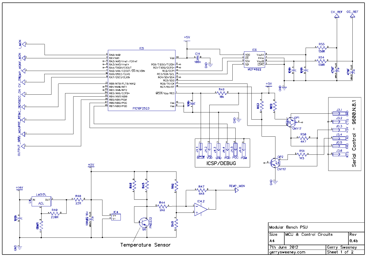
Here is the schematic diagram for the prototype I am using.
For the dithering I have decided to extend the DAC by 2 bits. Extending by two bits means I have to write a sequence of four codes continuously in succession to the DAC. I am writing approximately 1000 codes per second within a timer driven high-priority interrupt routine which ensures that the timing remains constant. Timing errors will introduce more DNL errors so the code stream needs to be constant and accurate. The codes written are the base code value followed by the base code value + 1. The two least significant bits from the now 14-bit word controls how many times each of the two values is written. For example, to get four steps between code 100 and code 101 we would write the following codes: –
100.00       100   100   100   100
100.25       100   100   100   101
100.5        100   100   101   101
100.75       100   101   101   101
Extending by 3 bits is an option and would mean I have to write a sequence of eight codes, again following the same explanation as above, here are the codes that would be written
100.00        100   100   100   100   100   100   100   100
100.125       100   100   100   100   100   100   100   101
100.250       100   100   100   100   100   100   101   101
100.375       100   100   100   100   100   101   101   101
100.500       100   100   100   100   101   101   101   101
100.625       100   100   100   101   101   101   101   101
100.750       100   100   101   101   101   101   101   101
100.875       100   101   101   101   101   101   101   101
I tried the three bits as an academic exercise but I have decided not to go to three bits because of the noise, ripple and integral errors generated. The cost of the filter circuitry and the expansion of the line items in the bill of materials would probably outweigh the cost of upgrading the DAC component to a higher resolution part.
I have selected a number of spot voltages in the range to benchmark what I get from the DAC. The following table sets out the results I measured. (I am using a calibrated HP 34401A meter for all measurements).
| Spot Voltage | DAC Code | Measured MCP4822 (12bit static) |
Error | DAC Code | Measured MCP4822 (14bit dith) |
Error |
|---|---|---|---|---|---|---|
| 0 | 0 | 0.0015V | +0.0015V | 0 | 0.0014V | +0.0014V |
| 0.001V | 1 | 0.0015V | +0.0015V | 4 | 0.0016V | +0.0002V |
| 0.002V | 2 | 0.0024V | +0.0014V | 8 | 0.0026V | +0.0006V |
| 0.003V | 3 | 0.0034V | +0.0004V | 12 | 0.0036V | +0.0006V |
| 0.004V | 4 | 0.0044V | +0.0004V | 16 | 0.0046V | +0.0006V |
| 100mv | 100 | 0.1024V | +0.0024V | 400 | 0.1026V | +0.0026V |
| 500mv | 500 | 0.5024v | +0.0024 | 2000 | 0.5026V | +0.0026V |
| 501mv | 501 | 0.5034v | +0.0024 | 2004 | 0.5036V | +0.0026V |
| 1V | 1000 | 1.0004V | +0.0004V | 4000 | 1.0006V | +0.0006V |
| 1.5V | 1500 | 1.4975 | -0.0025 | 6000 | 1.4977V | -0.0023V |
| 2.5V | 2500 | 2.5014 | +0.0014 | 10000 | 2.5016V | +0.0016V |
| 3V | 3000 | 2.9993 | -0.0007 | 12000 | 2.9995V | -0.0005V |
| 3.001V | 3001 | 3.0002 | +0.0002 | 12004 | 3.0005V | +0.0005V |
| 3.002V | 3002 | 3.0012 | -0.0008 | 12008 | 3.0014V | +0.0006V |
| 3.9v | 3900 | 3.8968 | -0.0032 | 15600 | 3.8969V | -0.0031V |
| 4.095v | 4095 | 4.0916 | -0.0034 | 16379 | 4.0916V | -0.0034V |
Well, that is disappointing given I am aiming for a precision of 1mV and to get a control voltage of 0-6V I need accurate 500µV steps. So whats wrong here? Having read the data sheet there are some gotcha’s that naively you might ignore as I did. Every DAC has two really important parameters called Integral Non-linearity (INL) and Differential Non-Linearity (DNL). The DNL defines the maximum deviation to expect from the “ideal” voltage for any given code, expressed in LSB’s (or counts from ideal) and INL is the accumulated DNL errors that occur over the whole range. Fundamentally, the DAC is based on a resistor string network and its not easy to make highly accurate resistors, as soon as you start needing more accuracy the cost of the part rises very steeply, and even with the best part money can buy there will still be errors. The more bits you extend the DAC by using dithering, the more error you introduce and the more noise you introduce too. While extending by two bits is probably acceptable with a decent low-pass filter, extending by three bits and beyond is not really practical. As an aside, the noise figures for the MCP4x22 parts are not that great – something one must consider when the reference voltage generated is going to be amplified, the noise will also be amplified.
In summary then, I want accuracy and precision but I want reasonable cost and even if I spend a lot of money I will still have errors. The lesson learned for me is I now no longer think of a DAC as an accurate programmable voltage source – it’s not, it is a close approximation only. The MCP4922 (MCP4822) is a nice part for the $$$ and useful for some things I have no doubt, but it’s not good enough for what I want to achieve in this project. Even with the resolution extension to 14-bits it falls short. Actually to be fair, even with the errors in the DAC this would be make a pretty good degree of control, it is probably more accurate than most of the lower end bench PSU’s out there, but my benchmark is the Agilent E3631A so I need to achieve much better than this. The MCP4x22 device is the best resolution DAC Microchip do so I must now search for other parts instead – Linear Technologies and Analog Devices are the logical starting point for my search.
There is one further possibility which I have yet to try, which is to combine both 12-bit DAC outputs to create a much higher resolution DAC, the block diagram for such a solution is shown in the data sheet for the part. This is well worth a look because if it works well enough, the cost of the two chips may well still be cheaper than an upgraded DAC part. I will build this out at some point and give it a try.
This project also needs to implement metering in order to monitor the output volts and current drawn by the load connected to the PSU, and this needs to be reasonably accurate to 1mV too, that’s 5-digits I need which in its self is a tall order. However, it occurred to me that if I could get an ADC that was accurate enough and a DAC with enough resolution to provide headroom for trimming it might be possible to build a self-calibrating system that trims the DAC output to match the desired programmed voltage each time you set a new voltage. That is what I will look at in Part 8.
This content is published under the Attribution-Noncommercial-Share Alike 3.0 Unported license.
Gerry,
Minor observation, in the 1st section were you show the range of 4 sequential values to
output in order to create the dithered fractions ie:
100.00 100 100 100 100
100.25 100 100 100 101
100.5 100 100 101 101
100.75 100 101 101 101
Would it be a benefit to change the 100.5 from
100.5 100 100 101 101
INTO
100.5 100 101 100 101
This would make the ripple frequency look twice as high and give a smoother output
from the low-pass filter all though how much effect that would actually make of course
depends on the filter and it wont change the other values.
Hi Span,
Yes thats a very good point, that would optimise it nicely and give the filter less work to do in the case where a 0.5 code is being applied. Unfortunately the filter still needs to handle the other cases too but this improvement is worthwhile none the less. Thanks for the suggestion.
Gerry
Hi Gerry,
I just came across your PSU project today and I am fascinated. I have been looking around for some time for a good DIY bench supply. It is ironic because my (limited) capabilities are in analogue circuits: I know nothing about microcontrollers (and thus, you’ll be pleased to know, I have no basis whatsoever to second guess your choice of controllers). The use of a microcontroller may offer the solution to my nagging problem.
One of the problems I’m having with my design is heat dissipation. From the tear-down you did of the HP E3631A, I see HP chose to use forced air across heatsinks the size of a Hummer to cool the pass devices. I would like to avoid forced air for two reasons: it is wasteful and inelegant. The IRF540 has a junction-to-case thermal resistance (Rθjc) of 1.64. For a robust service life, the junction temperature should be kept below 100° C (and lower is better). That is not easy. In the 0-30 volt mode, for example, if the output is set at 3 volts and the load is drawing 1 amp, and further assuming 5 volts of headroom for the regulator, the pass device has to dissipate 32 watts (i.e., 35-3 volts times 1 amp). To keep the junction of the IRF540 below 100°, the heatsink (without forced air and assuming 25° C ambient) has to be rated at 0.2 (i.e., Tjnc-Tamb/P – Rθjc ̶ Rinterface). That is a huge heatsink. I have tried to deal with this in two ways: first, I’m looking at a pass device with a lower Rθjc. The MJ802/MJ4502 (a BJT, not a MOSFET) has a Rθjc of .875 (http://www.onsemi.com/PowerSolutions/product.do?id=MJ4502). That helps. Now the heatsink has to be rated at 0.9, which is big but available at a reasonable cost. http://www.heatsinkusa.com/10-000/
Second, I have been trying to devise a way to correlate the voltage into the regulator to the required output voltage. I believe HP and others in the past, used different taps on the power transformer depending on the required output voltage — you could hear the relays clicking as you swung through the voltage range. I could use a couple of opamps as comparators to drive relays, but a microcontroller might be simpler.
Keep going. It’s great. I look forward to the next installment.
All the best,
George
Thanks for looking at my blog, glad you find it of interest. The noise aspect of forced air cooling is off-putting but it can be managed with some simple temp monitoring and fan control. For a bench PSU I like the idea of forced air cooling because properly managed an idling fan can not even be heard, a slight breeze is all thats needed. However, when you put a big load on and start to dissipate power as heat then I can forgive the fan noise in exchange for bench real estate gained. I ran into thermal problems with the IRF540, its not really up to the job for the exact reason described. I have since changed the design to use an IRFP240 which is a much better device. That being said, I have a plan to also try a BJT device TIP36C too, have to play around a bit with that. On the 30v range the very best thing to do in order to lower heat dissipation of the pass device is to pre-regulate and thats what I am building in, essentially is a charge-pump using the reservoir caps and switching on the AC cycle. The technical problem to overcome is to deal with the PSU’s dynamic response when a big power demand is placed on the output, I have not got to this yet but its on the agenda.
Regards,
Gerry
There is a way of dithering that reduces the effects of both DNL and INL. Instead of twiddling just the least significant bit or two, span larger sections of the DAC’s scale. That way you average out the DNL. Say instead of going -0,+0,+1, go -32,+32,+33 or -64,+64,+65. The effect is the same, only the output analog filter needs to have more rejection. The average of (-0, +0, -0, +1) is 1/4, same as (-64, +64, -64, +65). The average of (-0, -0, +1, +1) is 1/2, same as (-64, -64, 65, 65). If you have enough code memory, you can have an interpolation table to calibrate out some INL as well. The INL won’t change much after the DAC is made, so that should work, perhaps with a bit of aging of the DAC.
Hi Kuba, I did try spanning a larger part of the scale and as you rightly say the filter has to be good because the magnitude of the ripple created becomes significantly more apparent. Actually the DNL in averaging between two codes has not really been a problem, its where the DNL impacts the real code thats been a problem. I was thinking about a code adjust table to tackle the INL but for the steps I need that is a lot of controller flash (6k in my case) and I was put off because I would need some special rig for calibration as each DAC chip would need calibration – in production this would be a poor design choice because if a PSU went out of cal – the special setup would also be needed by the user or ship back to me.
Gerry,
With respect to the current sensor chip, just noodling around on the ‘net, I found the B-B INA138, http://www.ti.com/general/docs/lit/getliterature.tsp?literatureNumber=sbos122c. It will work with Vin down to zero. Also you can set the gain with a single outboard resistor. I also found the TI INA209, which also work down to zero. http://www.ti.com/general/docs/lit/getliterature.tsp?literatureNumber=sbos403b. It also measures voltage and has an I2C interface. I have no idea if the internal ADC has sufficient resolution for your purposes. As mentioned, digital is not my domain.
George
Hi George. I had looked at the INA138 but cost was a factor there, the MAX4080 is low cost and seems to do the job nicely so I did not look any further – I may well do when I come to look at manufacturing costs. I have not established how close to zero I can get with the MAX4080 as of yet, but I expect it do do the same, I suspect they are very similar internally but the MAX4080 has the resistor built in and pre-set. I don’t like the INA209 device for this purpose its only a 12-bit ADC for a start and you will see from the next couple of articles thats not really good enough. Actually the INA209 has a very specific design target which is automotive so the max 26v would not be up to what I am trying to achieve. Gerry