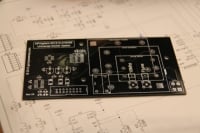
Having obtained a reasonably reliable 10MHz lab reference (see here) I decided to calibrate my Frequency Counter only to find that the stock oscillator provided in the HP 53151A is absolutely terrible – a joke even! I looked around for an “010 High Stability Timebase Option” but they are rare — and if you can find one not installed in a counter they are very expensive – in the few hundred dollars range at least — and buying one from HP is, well, expensive in the extreme. There are many second-hand 10MHz OCXO modules available, these are mostly stripped from old telecommunications, satellite or cellular equipment so they are plentiful and relatively cheap to buy too. I decided to make a clone 010 option board for my counter using a second-hand OCXO bought from e-bay. I designed a PCB to get a professional finish as well as a reliable upgrade for my counter. The main goal was to make an option board that just like the original could be automatically calibrated using the internal software and front panel controls so I had to use the same DAC chip (which is now obsolete) and basic topology of the original option board to make it work.
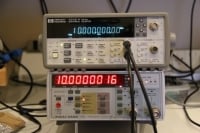
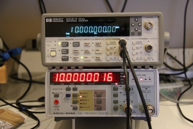
The result speaks for its self – with the OCXO running as the timebase, the counter is able to measure the 10MHz source it was calibrated with to a precision of 100th of one cycle with no error!
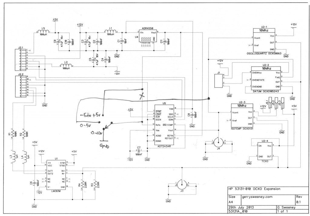
The schematic is pretty simple and self-explainatory. The counter seems to need a differential square wave clock drive, this is created using a high-speed differential output comparator part LM361. The DAC is an AD7243 part from Analog Devices, this part is now obsolete and not recommended for new designs but they are still available from various sources, albeit quite expensive parts. It would have been possible to design in a newer part but for the small number of units I wanted to make, it seemed a bit pointless to go to the effort as the recommended newer part actually requires different serial signaling, and this would have required some kind of serial protocol converter microcontroller. The DAC is driven by the counters microprocessor to calibrate and tune the timebase. The ADR4550 provides a high stability 5V reference for the ADC. The rest of the circuitry is basically power supply and signal filtering.
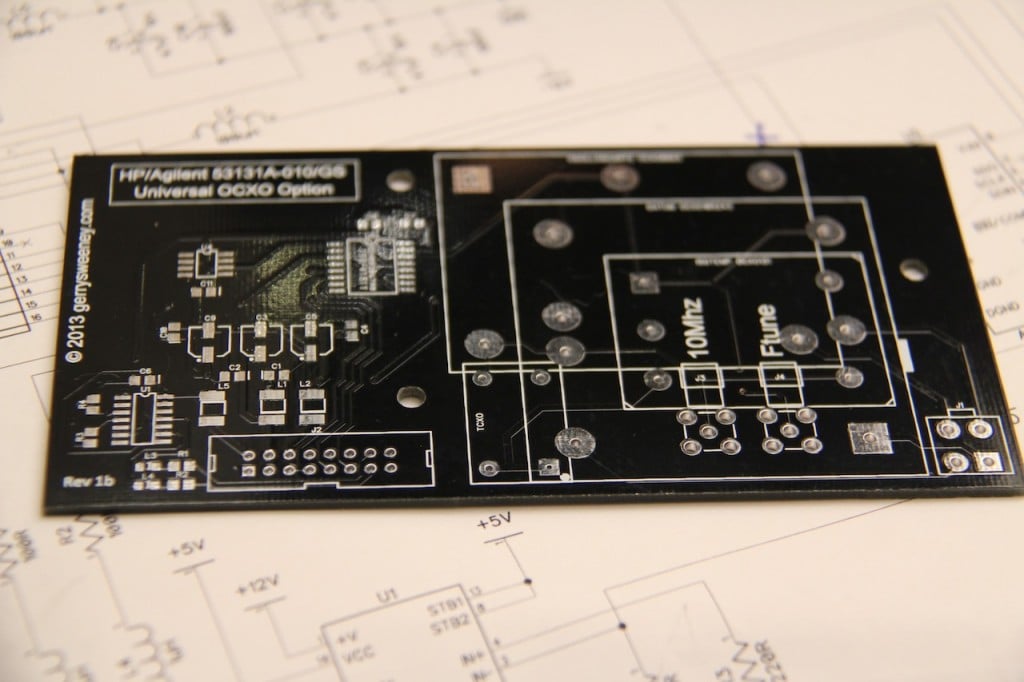
The PCB layout was designed to accommodate different OCXO footprints making it flexible. As well as supporting OCXO’s there are footprints for SMA connectors and you can even use a low-cost TCXO which cannot be automatically calibrated but is still a considerably better option than the oscillator built into the counter.
PCB’s Available : See here
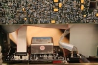
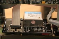
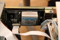
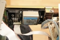
The finished board fits really neatly inside the counter, and even fits around my previous Hard Power Switch Modification project.
Various Pictures
Catch you next time….
