Following on from the project to build a DIY OCXO upgrade option for my HP/Agilent 53131A Frequency Counter I had a large number of requests for me to make the PCB’s available so others can built there own. I now have some PCB’s and are making them available for sale. I will also be making some fully assembled and tested/verified boards including an OCXO, ready-made cable and mounting stand-off’s, there will only be a limited number of these so if you are interested, let me know, first come first serve and when they are gone they are gone.
Now, someone made a comment on hackaday stating that the reason why these OCXO’s are on e-bay is because they are no good. Well I can understand why one could draw that conclusion but having now played with in access of 50 of these OCXO’s I can tell you that they all pretty much violently agree with each other and they also agree with the Rubidium Frequency Standard I have, so given they are from different sources and all free-running I am pretty comfortable they are good and usable quality devices. I read a lot on the net about “burn in time” and the general consensus seems to be, the longer you age and heat a crystal oscillator the more stable (in terms of drift) it becomes. Now I don’t know how true that is, but if it is true, then by definition, using recovered OCXO’s must actually be a good thing. Of course if you feel the need to pay a couple of hundred dollars for a new OCXO then you can of course do that – but I am pretty sure that it does NOT guarantee you any better performance, it just buys you the right to get compensated if you happen to find it does not meet the performance specifications quoted by the manufacturer and it might make you feel a little more confident. Anyway I guess the results speak for themselves and for a home lab these OCXO’s are more than good enough I think.
Here is a short video showing the various configurations built and working as well as a quick overview of the PCB its self and the configuration options.
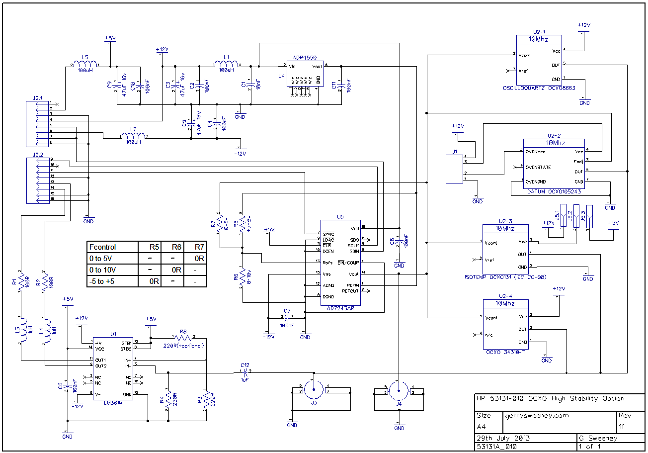
The Schematic
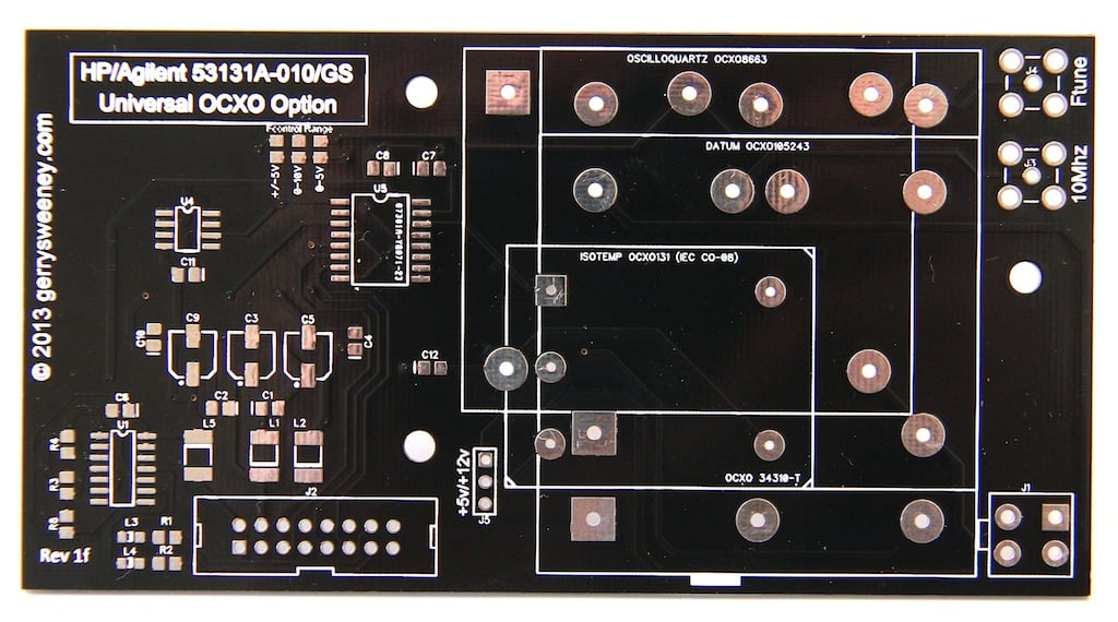
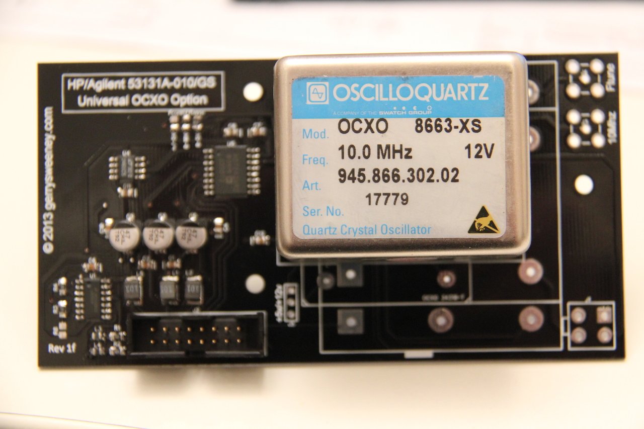
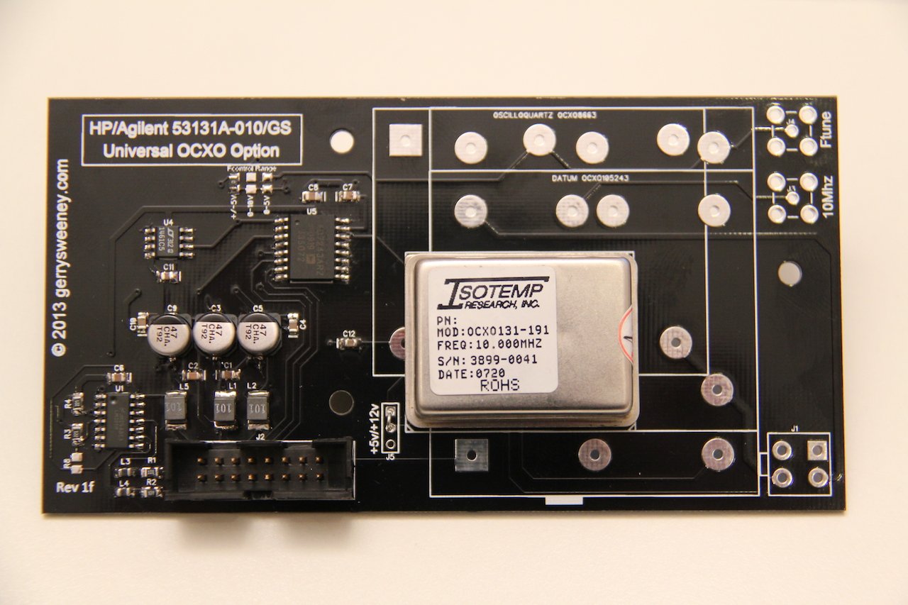
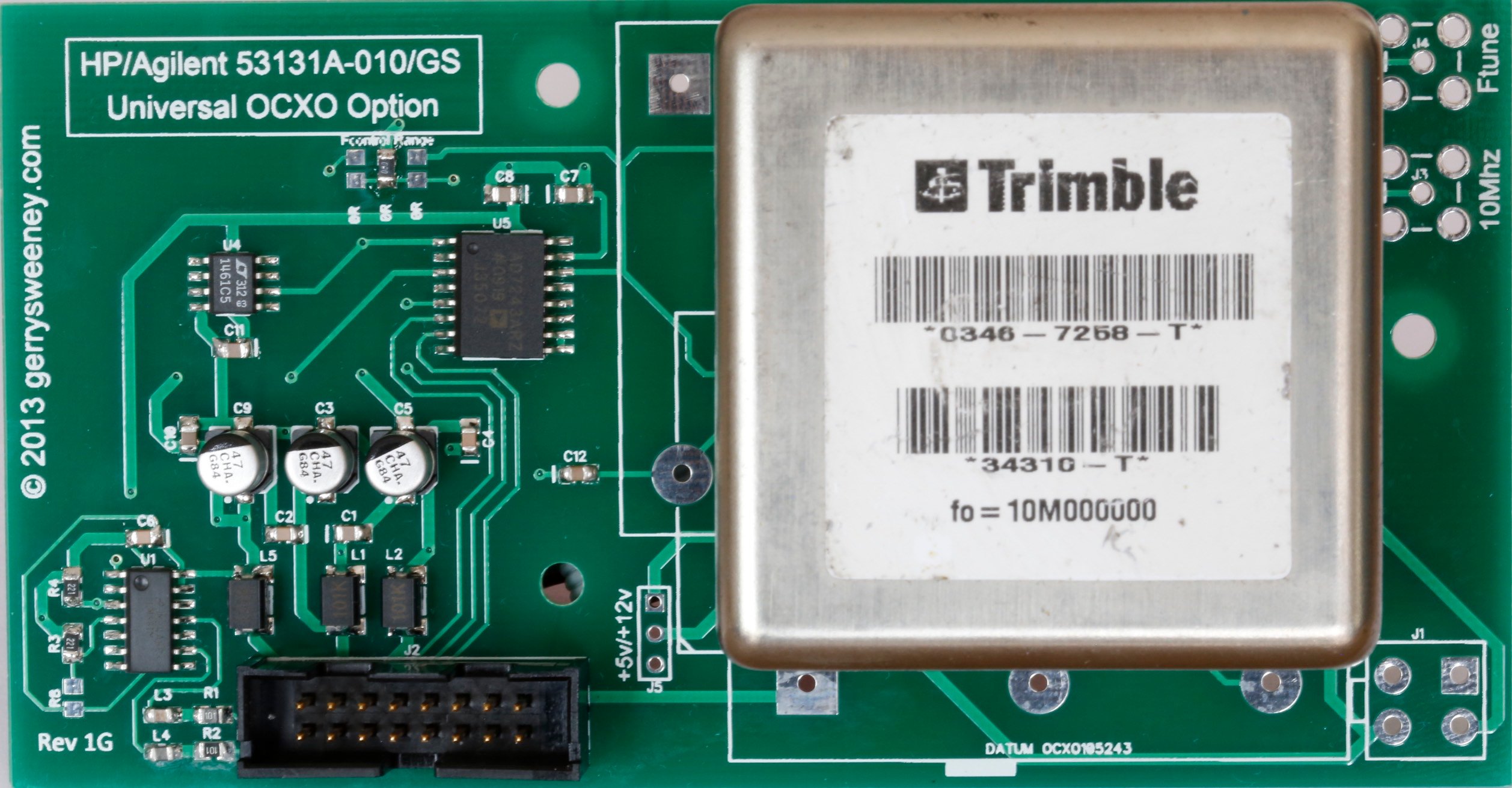
The PCB
This is the revision “1F” board. When I designed the board, I picked a few of the OCXO types that are available on the second-hand (salvaged) market and designed it to accommodate these. My original plan was to support four types of OCXO, the Oscilloquartz 8663-XS that I used in my own counter, a Datum 105243-002, and Isotemp OCXO-131 and a Trimble 34310-T(2). However, when I laid the board out I did not have the Trimble 34310-T(2) device to hand and made a (wrong) assumption about the footprint – which is a bad schoolboy error I know – the upshot being that while this board has a footprint and markings for the Trimble 34310-T(2) it does not fit, the pins are about 1mm out and therefore the board IS NOT suitable for that particular device. It is feasible to drill holes, the pads are just about big enough but assuming there is some demand for these boards I will order a second batch with the footprint corrected.
The following OCXO’s are known (and shown in the video) to work. Any others might work but thats up to you to verify 🙂
- Oscilloquartz 8663-XS
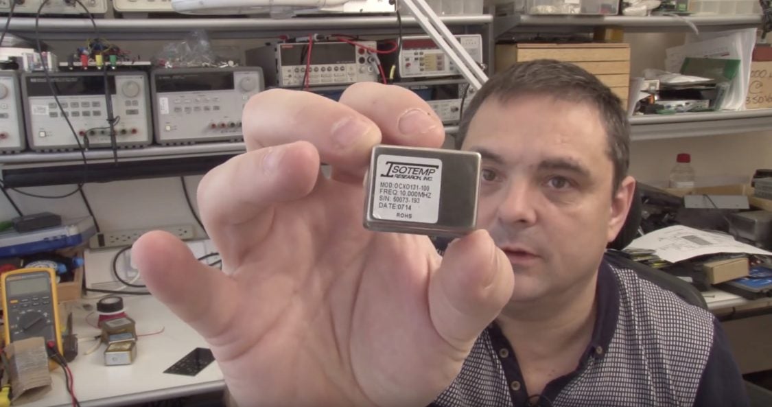
- Isotemp OCXO131-100
- Isotemp OCXO131-191
- Datum 105243-002
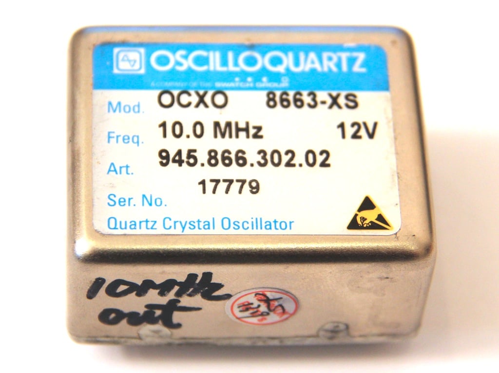
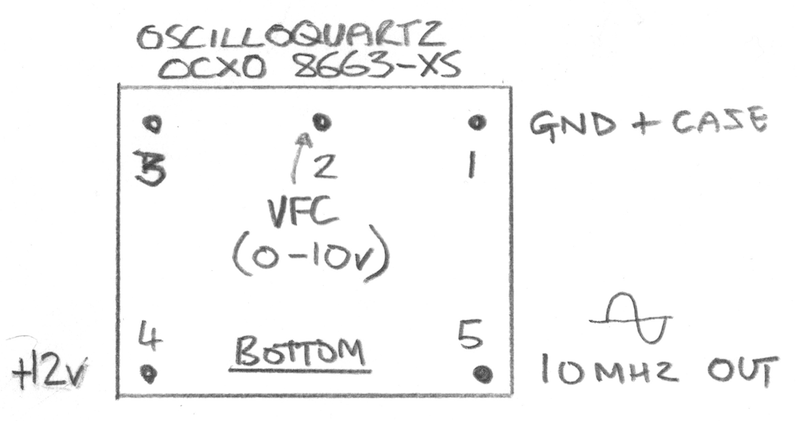
Oscilloquartz 8663-XS
This is the first OCXO I used, its more expensive than most and seems good quality and very precise. It works off of 12v and provides a nice clean sine wave output. The voltage control input works on the 0-10V range. I could not find any data on the XS version so I don’t know what its performance specifications are. I have included a download for this device but it does not cover the XS version specifically. The data sheet states that this device requires 0-10v for the frequency control, and testing seems to bear this out too. However, to get the counter to calibrate properly I selected the 0-5v range on the DAC.
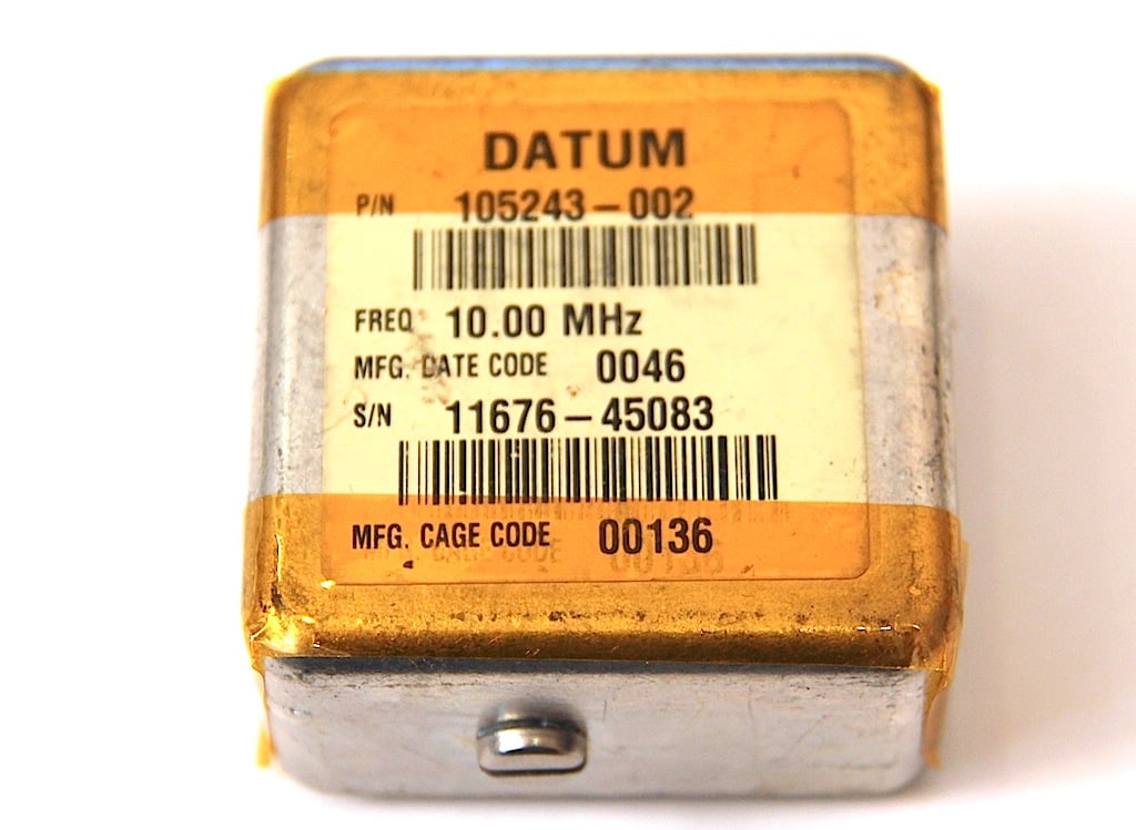
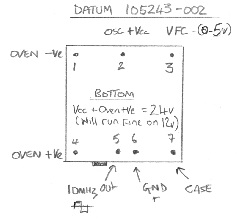
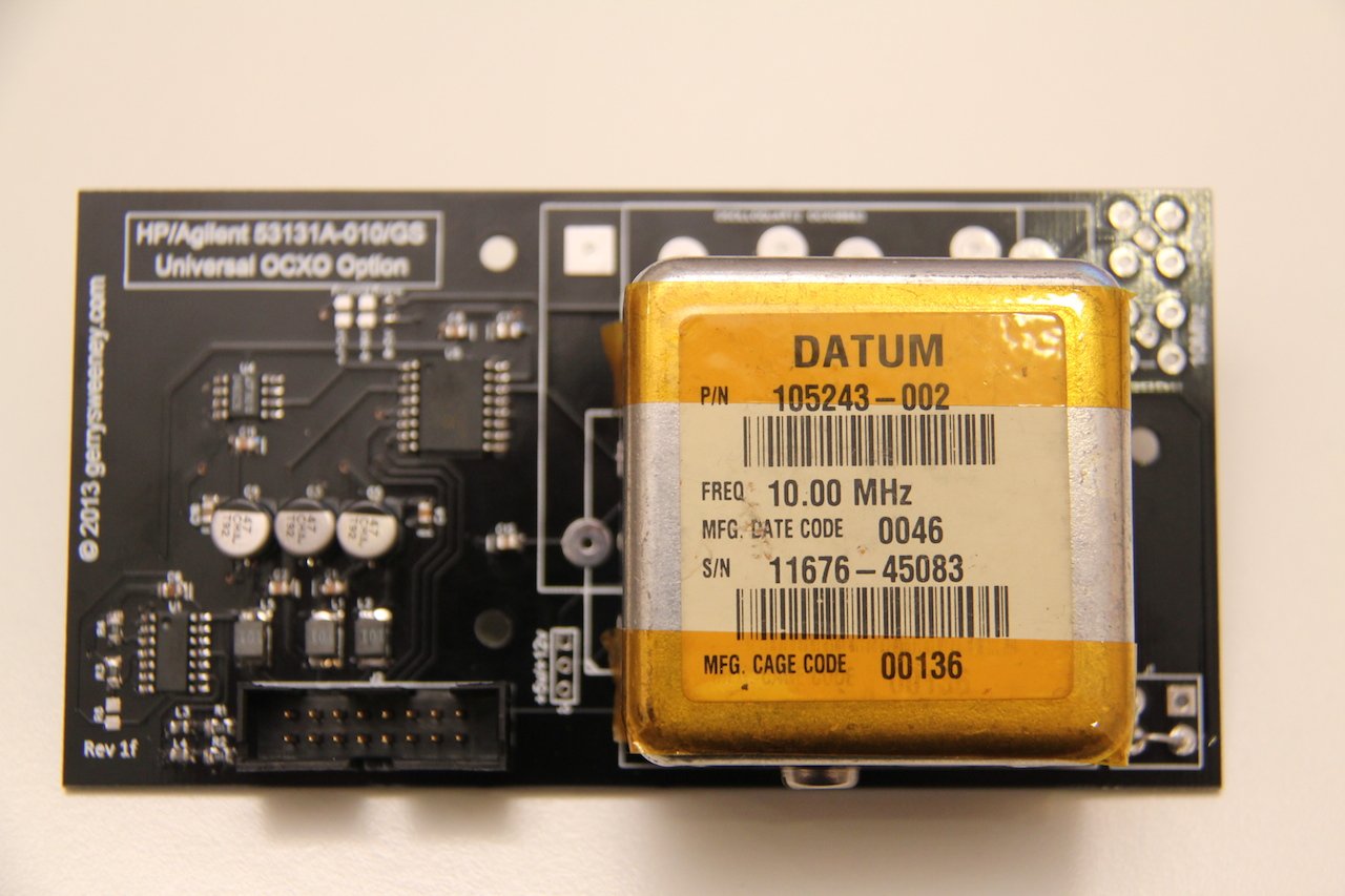
Datum 105243-002
This was another OCXO that I included on the board for Andy (who built the first 3Ghz pre-scaller option board), again a nice device but its specified to work on 24V and the Oven and Oscillator have separate power connections. This is the only OCXO that has a built in trim pot which allows you to set the window for the voltage control range. Although this device is specified to run at 24V, I tested its operation at 12V and it works perfectly. I did put a four-pin plug onto the board to allow you to give it a separate 24V supply but it really does not need it. I do not have any data sheet for this device but it outputs a square wave which is not as nice as having a sine wave on the output – but for this application it does not matter at all. The Frequency control input on this device is very sensitive and while it works without problem at +/-10v its centred around 2V and 0-5v works just fine.
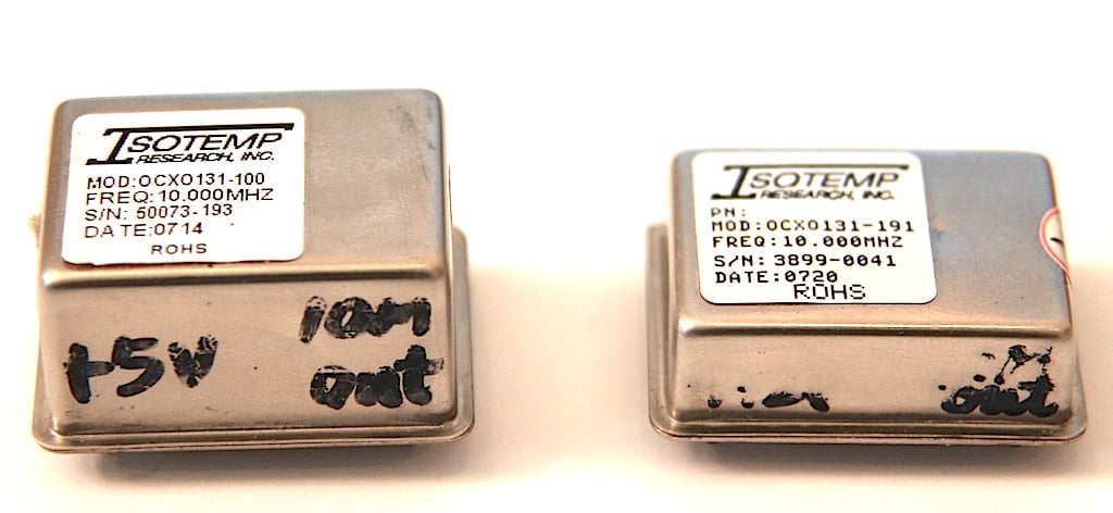
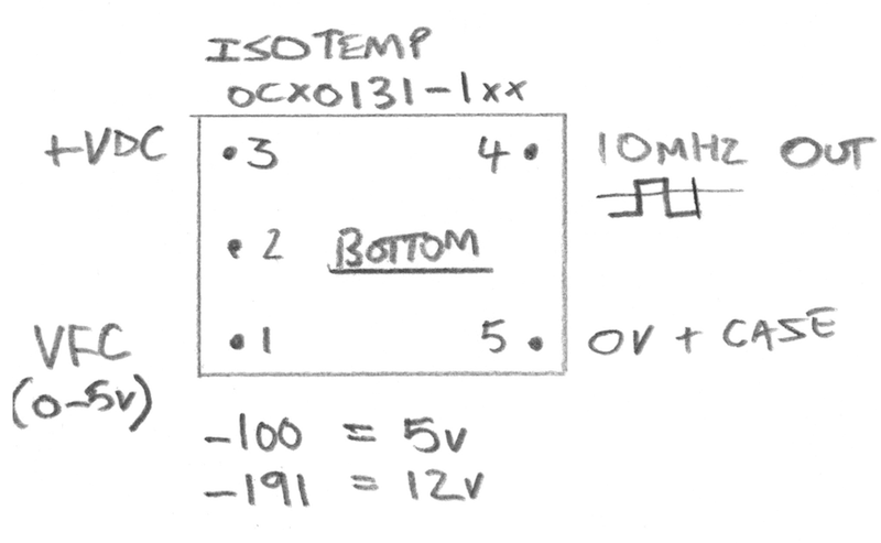
Isotemp OCXO131-1xx
This is a small, compact device and comes in two variants, the OCXO131-191 which is a 12V version and the OCXO131-100 which is a 5V version, and while both share the same PCB footprint and pinouts the case for the 5v variant is taller at 18mm high where as the 12v version is a compact 11mm high. These also provide a square wave output. Both versions of the device require 0-5v on the frequency control input although to get the counter to properly calibrate I had to configure it for the +/-5V option.
Kit of Parts
Some people asked me about providing a kit of parts. I am not really geared up to do that in a time-efficient way so apart from the bare PCB, I will not be able to provide individual parts or components.
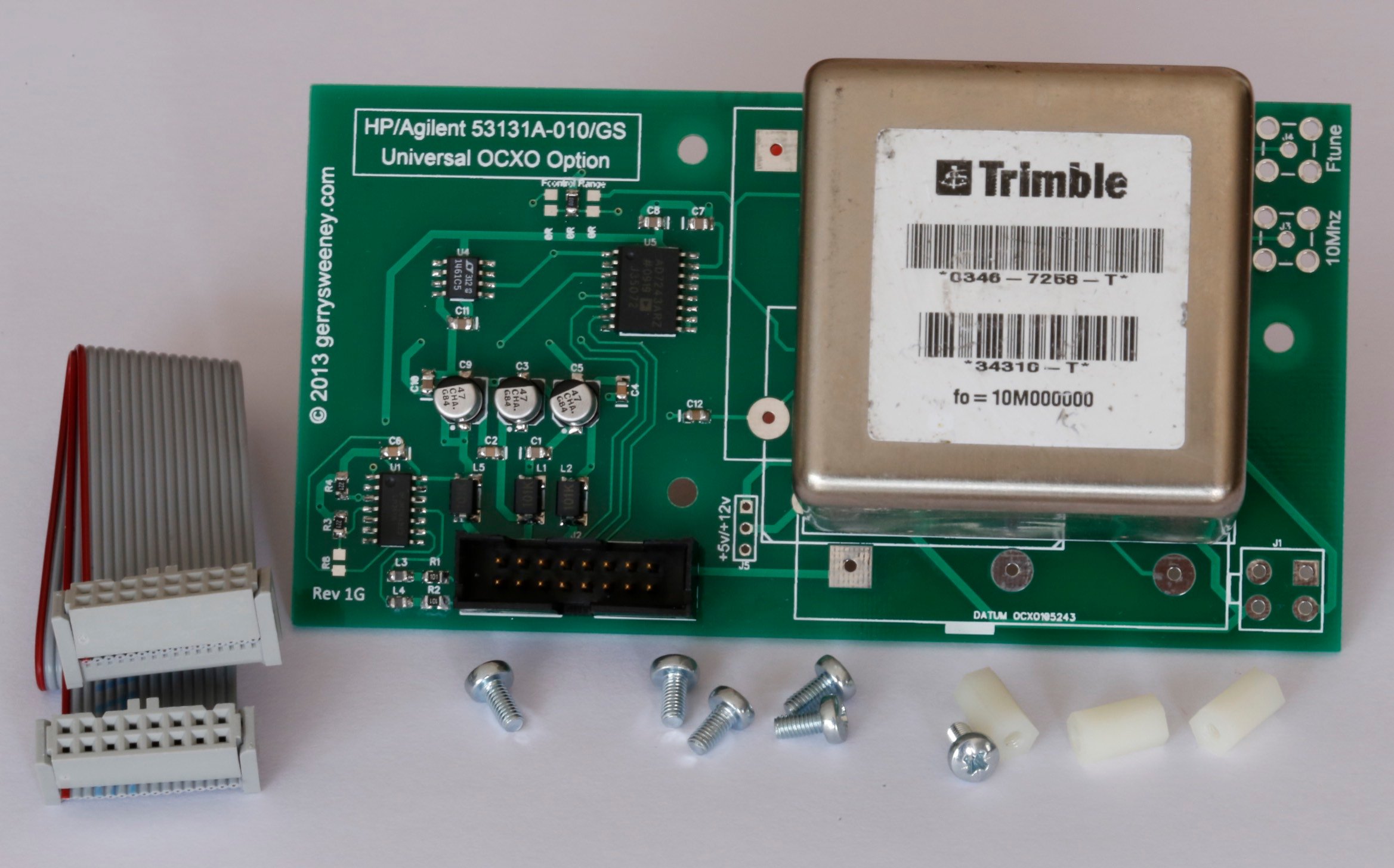
Fully Built and Tested Option
I am planning to have a limited number of these option boards fully built and tested with all the components and the OCXO pre-installed as well as a suitable cable and mounting stand-off’s, ready to install and use in your counter 531xx HP counter. I do not have an exact cost for these as I still have to source some of the components but they are likely to be be in the £75 to £95 range. I will post an update when I have these available which should be in about 2-3 weeks time.
UPDATE: I now have some fully assembled and tested boards complete with cable and mounting parts needed for a simple plug-and-play 53100 series counter upgrade. I am providing these with a Trimble 34310-T OCXO which is a really high quality, high spec double-oven OCXO, performance compares very favourably to the original high end option offered by HP at 10x the cost
Bill of Materials
| RefDes | Part No | Notes |
|---|---|---|
| C1, C2, C4, C6, C7, C8, C10, C11 | 100nF | 0805 SMD Jellybean part |
| C12 | 1uF | 0805 SMD Jellybean part – Could probably use 100nF with no problem |
| C3, C5, C9 | 47uF 16v | Electrolytic. Farnell Part No: 197-3305 |
| J2 | IDC2X8M | Farnell Part No: 231-0066 |
| L1, L2, L5 | 100uH | Farnell Part No: 935-8056 |
| L3, L4 | 1uH | Farnell Part No: 221-5638 |
| R1, R2 | 100R | 0805 SMD Jellybean part |
| R3, R4 | 220R | 0805 SMD Jellybean part |
| R8 | 220R | 0805 SMD Jellybean part – This is not needed unless you want to mess with the comparator bias |
| U1 | LM361M | Very fast differential comparator |
| U4 | ADR4550 | You can use a REF02 or numerous other 5V reference parts here, the pinout is pretty standard |
| U5 | AD7243AR | This is the most expensive and hard to get part |
Bare PCB’s Available
UPDATE: After my first trip to the post office today I have had to amend the pricing because of the outrageous postal charges, I have been told that I cannot send something that’s not made of paper as a letter! that means for my friends outside of the UK the postage is more expensive, sorry about that. The good news is, the postage does not go up with the number of boards. I hope you understand.
UK Orders
If you want more than two boards please contact me directly via e-mail because the weight starts to impact postage.
| STILL AVAILABLE 1 x HP/Agilent 53131A-010/GS OCXO Option Bare PCB Rev 1H inc. Postage | £12.50 | |
| STILL AVAILABLE 2 x HP/Agilent 53131A-010/GS OCXO Option Bare PCB’s Rev 1H inc. Postage | £23.00 | |
| UNAVAILABLE HP/Agilent 53131A-010/GS Rev 1G Fully Built and Tested with Trimble 34310-T OCXO, Cable and Mounting Kit | £145.00 + £10.00 shipping (tracked and signed for) | Contact Me |
Non-UK Orders
If you want more than two boards please contact me directly via e-mail.
| STILL AVAILABLE 1 x HP/Agilent 53131A-010/GS OCXO Option Bare PCB Rev 1H | £15.00 | |
| STILL AVAILABLE 2 x HP/Agilent 53131A-010/GS OCXO Option Bare PCB’s Rev 1H | £27.50 | |
| UNAVAILABLE HP/Agilent 53131A-010/GS Rev 1G Fully Built and Tested with Trimble 34310-T OCXO, Cable and Mounting Kit | £145.00 + £18 shipping (tracked and signed for) | Contact Me |
This content is published under the Attribution-Noncommercial-Share Alike 3.0 Unported license.
I’ve used a few C-MAC branded OCXO’s purchased from eBay and found those to be ok too, a few of them are very slightly off the 10MHz value however a slight tweak via the VFC pin puts that in order.
cheers
John (youtube – orbiter8)
Hi John,
Thanks for the info.
Gerry
Gerry, I would be interested in buying two (2) assembled boards. I have a few of the Oscilloquartz 8663 xs oscillators already. So, I could buy the boards assembled and with cables, but without the oscillators, if that would leave some oscillators for others. Jim N1JR
Hi Jim, I was planning to provide the OCXO’s too, I have a bid in for a number of OCXO’s and have just about enough parts to build the boards, I will see how it goes, if I can provide you with boards minus the OCXO’s I will. Gerry
Add me to the list for the assembled version Gerry….too many other projects to work on in the queue! Will check out eBay to get a OCXO in anticipation of the populated board (or will you be including it?).
Dino
Hi Dino,
I will be providing the OCXO on the assembled boards. If I am to get this sort of thing assembled I want to male sure each item works in totality so I don;t have to deal with returns of part completed boards. For simplicity if I provide the whole thing assembled I know that it works and calibrates properly.
Gerry
Gerry,
If you need to supply the “built” boards with oscillators, I will be glad to buy two of them with your oscillators (instead of using mine). So, dealer’s choice. (i thought that using my 8663-XS units might be of help to you and others.) Jim, N1JR
Hi Jim, ok thanks, I will let you know what works best. Gerry
Gerry,
Always looking for new ways to reference lab equipment. Will you be shipping un-populated boards to the States?
Thanks
Hi John,
Yes the cost includes postage to any location.
Gerry
Gerry, you might add a BOM with Digikey part numbers or something, just to make it simpler for some to get the correct SMT parts.
Andy, yeah thats a good point, I will do that. Gerry
Just ordered a bare board (transaction ID for this payment is: 6T8982723G793422U). Are there any hard to find parts that I will have trouble sourcing here in the USA? If so, have you considered offering those parts at extra cost?
Thanks.
Hi John, all the parts are available from the likes of Digikey, Newark etc..so should not be a problem. I am not really geared up to offer individual parts, I want to avoid the best I can becoming a logistics operator 🙂 I am waiting for some cardboard envelopes to arrive, should be here in the next couple of days, once I have them I will post the board. Gerry
will you be shipping to US?
Yes the cost includes postage to any destination that has ground mail. Gerry
hi
I updated the sch divider up to 12 GHz 🙂
There is also a PCB design 🙂
http://www.rflab.pl/projekty/DIVIDER12GHZ/DIV12GHZ.htm
Now I just have to make PCBs have little problems with the laminate PCB
Hardly anyone takes PCB to RO4003C 🙂
That looks great, will be interested to see how it comes out and if it works. Gerry
Hi Gerry
Thanks for the good word, because is not it simple
One.
Service manual HP (Agilent) is a joke.
On each side of something else….
See pages 8, 20, 39, numbering pin connector J2 on each side of the other :)…
Two.
The divisor to 3 GHz by 128
But it’s 12 GHz should be 512, the meter detects this by J2-9 J2-10 (I think)
and …
Apply so different divider instead HMC394 will use uPB1505. This is a divide by 64
So the divider (I assume input frequency 12 GHz) HMC363 (/ 8) will be 1.5 GHz, then the divider uPB1505 (/ 64) is the frequency of 23 .. MHz
Gerry give a list of items (with the types / sizes of enclosures) (can excel?) Do list items by Farnell (Newark) to OCXO of course 🙂
Hi Marcin,
Sorry for the late reply, I have added a BOM to the blog article.
Gerry
Hi Gerry,
Thanks for the good work.
Having now got both the PCB and the OCXO, I really ought to build it up.
Is there a BOM anywhere ?
Hi Martin,
I have just updated the article and added a BOM – should have done it earlier – sorry about that.
Gerry
Do I owe you some more money because of the increased postage costs to US?
Hi John, no not at all, if you ordered a board before I changed the price I will honour that, all boards are sent out now so if you have not received it yet you should do very soon. Gerry
Slightly off topic – This month QEX from ARRL has an article on using GPS to to fine tune a rubidium frequency standard: http://www.arrl.org/files/file/QEX_Next_Issue/Nov-Dec_2013/Table_of_Contents_QEX_11_13.pdf
Thanks for the pointer. I have a Trimble GPSDO which I need to do a video on. I have been thinking about a Rubidium Disciplined OCXO to iron out the strange frequency jumping the RFS seems to put out too. Gerry
Hi Gerry,
Any progress on the availability of assembled boards?
Jim
Hi Jim, I have all the parts and boards now, I will be building one up and testing it today so assuming there are no issues I should be able to confirm. They will be £80 (excluding postage) complete and tested, provided with a ready installed Trimble 34310-T OCXO. Gerry
Another one up and running, worked great on my 53132A. Used the Oscilloquartz 8663-XS, mine failed cal as well on 0-10v, however 0-5v worked great.
Thanks again Gerry,
Andy
Good to hear Andy, glad it works. Makes a really big difference to the counter right? Gerry
Gerry, the two assembled boards arrived in good condition. I will install them later today. One question: the counters have “standard” TB already. Is there some standard TB cable or some other connection which I should “disconnect” when installing the High Stability TB? (I haven’t opened up the units yet, so I apologize if the answer is obvious.)
Jim
Hi Jim,
Great news, thanks for letting me know. You do not need to worry about the internal timebase, that is automatically disabled when the counter detects the external timebase.
Gerry
This option works very well
I used OCXO DATUM.
Deviation after about 1 hour does not exceed 0.020 Hz to 10 MHz.
Thanks
Gerry
Good Job 🙂
Hi Marcin,
Excellent, glad it works for you.
Gerry
Would it be possible to take the 10Mhz output and change the pulse width to about = 100 nsec and boost the voltage to 150V – 220V range using a timer and a coil ??
any advice or ideas are welcome… thankyou
I am not sure I understand the context of the question to be honest, sounds like you have a different project from what this design is intended for. Gerry
Gerry, Time bases received and one installed. It is working fine. Thank you for a great product. By the way, do you know if your friend Andy going to offer for sale the 3 GHz Third Channel that you made the video about? Jim Robbins
Hi Jim,
Glad you got them ok, nice to hear they are working for you. Its a really great mod for them counters. I am pretty sure Andy is not intending to make any of the 3Ghz boards. My plan was to do a board layout and get some PCB’s made but thats on the back burner at the moment due to other commitments.
Gerry
Sorry – I won’t be making any 3Ghz boards – I just have too many other commitments.
Gerry – if you want you can publish the design files ( if you no longer have them – mail me and I can re-send ).
Hi Andy,
Yes I still have the design files. My only concern with publishing the design is the issue with the connector – someone could *NOT* read the commentary and plug the thing in and damage their counter. I should probably re-layout the board or at least fix the connector so that its safer to make the boards.
Hope you got to the end of your building issues.
Gerry
When I get back in the country – I will send the updated design files with the corrected connector. The updated files have not yet been sent for production – so another warning would be needed 🙂
As for the building – that always turns into more work than planned (and the day job gets in the way)
Hi Andy,
Ok that would be great. Actually after I posted the comment I thought about it, I can probably make some edits myself. I now have an original 3Ghz so I can work out the exact footprint and have a go in KiCad. I have been real busy at work of late too, exciting but all consuming too..
Gerry
Here is the updated project
http://www.rflab.pl/projekty/DIVIDER12GHZ/DIV12GHZ.htm
Current status of the project:
PCB was soldered, I made the first tests.
Divider system works very well up to 4.4 GHz, the input sensitivity is better than -40 dBm. (I have not tested the range of 4.4 – 10 GHz)
There is a problem with frequencies above 10 GHz, the system does not work. Perhaps the reason lies in the resonances of the power supply (DC block) integrated circuits VMMK.
And
Currently, plans to replace the diode HSMS (Cf = 0.2pF) for MACOM MADS0013171500AG (Cf = 0.045 pF!), And apply any resistors type microwave (Vishay)
In addition, we are working on redesigning the power amplifiers VMMK. Supply system filter must have a minimum inductance and capacitance.
For example, the parasitic inductance and capacity of the value of 0.3pF and 0.4 nH! creates a series resonant circuit with a frequency of 10-12 GHz (effectively contains the correct signal)
Hi Marcin,
that project is looking really good, nice board and layout. excellent.
Gerry
Thanks Gerry 🙂
He works on the subject, general assumptions are correct, but the availability of “good” electronic components is difficult
Nice job on the 12Ghz board – you are a brave man working at that frequency 🙂
I hope you manage to achieve good performance.
thanks Andy
Still I correct PCB
Soon I will try to examine the divider to 9 GHz.
Important proved shielding PCB (High freq amp)
hey Gerry!
Just would like to wish you and your family a happy new year.
Hi Evan,
Thanks very much, may I also wish you and yours a happy new year too.
Gerry
Hi guys.
Recent studies divider,
http://www.rflab.pl/projekty/DIVIDER12GHZ/DIV12GHZ.htm
showed that:
In the range:
– from 200 MHz to 4.5 GHz sensitivity of – 50 dBm
– 4.5 GHz – 5 GHz, -45 dBm sensitivity
– 5 GHz – 6 GHz, sensitivity -40 dBm
– 6 GHz – 7 GHz, sensitivity-35 dBm
– 7GHz – 8 GHz, sensitivity -30dBm to -25 dBm
Not bad 🙂 As to the first such project “divider”
Now I have a new concept 🙂 divider up to 26 GHz 🙂
http://www.rflab.pl/projekty/DIVIDER26GHZ/divder%20up%20to%2026%20GHz.htm
Currently, work on using the ADF5002
Hi Marcin, thats really excellent progress…keep up the good work. Wow 26Ghz – do you have a siggen for that frequency? Gerry
Hi
The divider operates in a wide frequency range 4 – 26 GHz.
According to the Analog Devices chip operates from 4-18 GHz
However, the datasheet (page 6) shows that it should work properly in the field of 2-2.5 GHz (sensitivity – 10 dBm) to nearly 24 GHz (-10 dBm), 25 GHz (-5 dBm) 26 GHz ( 0 dBm)
Probably the company AD limited to 18 GHz specification in connection with the transmitted signal phase change (the system is applicable in the synthesis and stabilization systems-frequency)
ADF chip is also much cheaper than the HMC447 ADF – 18 $, HMC -50 $
The divider is designed for radio amateurs working in the microwave range, but not only 🙂
Hi Gerry! Where did you get those beautiful PCBs made? They look amazing!
Hi John, I used IteadStudio prototype service for those PCB’s. Gerry
Hi Gerry,
do you know if this board will work on a old HP 53181A?
I’ve got one of this today early, and not had time to search for the info. I saw your videos about this project, but if I remember, you have a 53131A.
Thanks.
HI Mario,
Yes it fits and works fine on the 53181A counters. Makes a big improvement to the usability and accuracy of the counter.
Gerry
Hi Gerry,
how much would cost to send a fully mounted and tested board to Brazil? what info do you need to get the costs?
Thanks
Hi Mario,
A fully constructed and tested board including a Trimble 34310-T OCXO module is GBP £80 – and shipping to Brazil (RoyalMail Air Mail signed for delivery) is GBP £16, so in total £96 – hope that helps.
Gerry
Hello Gerry,
Very impressive work you’ve done with the OCXO’s for the Agilent 53131A series. I was wondering if you know if the kit would be plug & play compatible with the newer replacement model 53210A (the particular unit that I have).
Thank you,
Scott
Hi Scott,
Thanks for the feedback. The answer to your question is I don’t know, I don’t have access to one to investigate and the schematics for the 53210A device do not seem to be available anywhere. I would guess they are not compatible though…
Gerry
Hello Gerry,
Thanks for the prompt response and info. Likewise, I don’t have access to the schematics so unfortunately I can’t help share any info in that regard. It’s interesting to note that there’s only one OCXO option (010 Ultra) with the new series, whereas the previous generation had the three options (001 Medium, 010 High, 012 Ultra) beyond the standard TCXO. If I should decide at some time in the future to break the seal and enter the until I’ll share what I can find out. Thanks again, and all the best.
Scott
Hi Scott,
Thanks for the info, I would be interested to find out more information, would be keen to know if its the same interface, although I doubt it is. I imagine the reason for only having one high stab option nowdays is there is no real cost differential, most OCXO’s are already very good nowdays…
Gerry
FYI: Dave Jones of the EEV Blog just did just did a blog post: EEVblog #647 – Agilent 53131A Frequency Counter Oven Upgrade at http://www.eevblog.com/2014/08/02/eevblog-647-agilent-53131a-frequency-counter-oven-upgrade/
Hi John,
Thanks for posting, I will post a link back to my articles on the EEVBlog forum. I should have sent Dave a board with a DAC on it…
Gerry
I Gerry,
Just installed in my 53181a, took about 15 minutes to have the unit up and running. All I can say remarkable job!
This option 010 is great!
Please let me know when Pcb for option 030 will be available.
Thank you again.
Hi Emanuele,
Thanks for letting me know, glad you like it.
Gerry
board (revision G) also works fine with Morion MV89 OCXO. Voltage control had to be jumpered to -5/+5V (leftmost jumper, jumpers are no longer labeled)
Goetz
Hi Goetz,
Thank you for posting and letting me know, nice to know it works with that OCXO too..
Gerry
Hi Gerry,
Are there any news about the opt. 030, boards, schematic / BOM or assembled?
If there is or would be later maybe you can send one to Dave (EEVblog) for him to do an review.
There is one video from TheSignalPath Blog on YouTube reviewing one opt. 030 from Poland.
I’m waiting for an good one to put on my 53181.
Thanks.
Hi Nuno,
I actually bought one of the boards from Poland and believe it or not I can’t find it!!! I am almost 100% sure it arrived in the post but biggered if I can find it anywhere – I think that signals a spring clean of the lab is called for…. I have not done anything further with the board that Andy designed, I really need to get to that, its been a long time now.
Gerry
Hi Gerry,
Please give design for Rohde & Schwarz 1100.5000.02 CMU-B11 Reference ocxo with ocxo 8663-XS
http://www.ebay.com/itm/Rohde-Schwarz-1100-5000-02-CMU-B11-Reference-OCXO-New-/321501101871?pt=LH_DefaultDomain_0&hash=item4adaf57f2f
Hi Mitko,
I am sorry, I do not have one of those and dont know anything about them so cant be specific. Most of these OCXO’s tend to be the same so it can almost certainly be made to work
Gerry
Gerry
Do you know if your OCXO will work on an HP5342A frequency counter?
Hi,
I suspect not, I think thats a totally different architecture. Not looked at the schematics but I doubt it would plug in and work.
Gerry
Hi, Thanks for the design. Could you spec the caps. Digikey can drown you in options when it comes to SMD caps.
Thanks
Hi Michael,
The spec of the caps are not that important to the design or accuracy of the unit, X5R on the 0.1uF they are just simple de-coupling, I will need to look the specific part numbers for the electrolytic, although the ones I fitted we marginally oversized for the footprint I used making soldering more challenging.
Gerry
Hi,
Thanks for the design. Are 16V rated caps enough for the small 0805 parts? How often are you able to get to the post office to ship these out? I ordered two.
Thanks!
Hi Michael,
Yes 16v parts should be fine, there is only +/-12v on the board. I will aim to post tomorrow.
Gerry
Hi, I received the boards today. They look great.
Does the crystal need to be spaced away from the board to prevent the soldering pads from shorting against the grounded case?
For a the occliloquartz, does the 12V setting need to be jumpered by shorting the top two holes of the voltage setting next to the 16 pin connector?
For a typical board, should R8 be left completely out?
Thanks!
Hi,
Glad you like them.
Yes I generally solder them wedging a couple of credit cards in the sides, then remove after soldering, that leaves a nice workable gap
You do not need any jumper for the oscilloquartz oscilator, just fit it
You do not need R8, leave it out and it will be fine
Good luck with the mod
Gerry
Just purchased an HP-53181A counter. Will your high stability circuit boards work in that counter and do you still have some bare or built boards left?
How is your home built programmable power supply project coming along, did you finish it. I like your videos, thanks for taking the time to make and post them.
Gary
Hi Gary,
Yes I still have some bare boards and fully built/tested units. Have recently been able to compare the boards I have built with the original board for these counters and I am dead pleased that the Trimble OCXO’s I am using are much better performers than the Isotemp fitted to the original, I plan to make a short video to show the difference because its quite noticeable. Anyway, as I said I have both so feel free to order what you would like. Thank you for you feedback on the videos, I appreciate, and more are coming I promise.
Gerry
Do you know if the Keysight 53220A can be upgraded with this board. If not any suggestions.
Thanks
Hi Bob,
No I do not believe it would work – one day I will get one of those counters and see if I can make one that does work with it -I get asked a few times.
Gerry
I ordered one of your fully built HP53131A, 53132A and 53181A time bases today. I am unsure if the price included shipping, if not send me the amount you need via email and how to pay you for it.
I received my HP-53181A yesterday, already ordered the 3GHz prescaler for Poland as the Signalpath.com tested it and it seemed to work great. Also purchased a few weeks ago and modified one of the Video Distribution amps like yours but am feeding it with my Trimble Thunderbolt, it works great. Had to stack 2 100 ohm resistors like you did, these 62 year old eyes had a bit of a time seeing them and not proud of the solder joints but I measured every one to the center of the op-amp and all 18 were 50 ohms.
Hi Gary,
Thanks for the order, I need to fix an OCXO and soak test so I wont ship until the end of the week, hope thats ok. I have one of the 3Ghz pre-scalers from Poland also, build quality seems good – I just seem to have misplaced it, my lab is a mess 🙁
Gerry
Hi Gerry,
I enjoyed your OXCO Videos.
I just purchased an HP 53131A and would like to buy one of your assembled HP/Agilent 53131A-010 OCXO Option boards for it.
Do you still have some for sale ?
Which OXCO is on the current boards ?
What is your current price shipped to OH, USA 44026 ?
Do you accept Paypal ?
Please advise.
Regards, Ken
Hi Ken,
Thank you for the feedback. Yes I have some available, the OCXO’s are Trimble 34310-T’s, they are actually very good and very stable, better than the HP original OCXO, I have sold many of these now with no complaints at all. I always soak test each one for 24 hours and make sure the cal range is good etc. Price is £80, postage tracked and signed to the US is £15, and yes I accept Paypal, you can use the buy buttons on the blog page.
Thanks for your interest
Gerry
Hi Gerry
I would like to purchase one of yourassembled ocxo’s for my HP53131 counter.. If they are still available, could you advise the total cost to send to Christchurch New Zealand.
once I know the cost I will pay with paypal. Many thanks.
Regards,
Paul Dixon
Hi Paul,
thanks for your interest. Yes I still have some available, postage to NZ would be £10 Royal Mail Air Mail, or £15 Royal Mail Tracked and Signed, I would suggest the later as there is some guarantee of delivery and item will be insured.
Please do be aware though I am current out of the country so will not be able to ship until the week of the 17th of August
Regards
Gerry
Hello,
I am from the US and am interested in possibly a full kit if not then just a board.
Do you still have them available and if so what is your current shipping to the USA?
Thank you
Sandra
Hi Sandra,
I have both bare boards and fully assembled and tested boards available. A bare board is £10, shipping to the US is £3. A fully assembled and tested board with cable and mounting parts is £80, shipping to the use Royal Mail tracked and signed for is £15. If you do order please be aware that I am unable to ship until the week of the 17th of August.
Thank you for your interest.
Gerry
Outstanding upgrade! The board was easy to install and fit perfectly. It’s very well made and I could not be happier with the results Gerry! Well done!
Hi Michael,
Superb! Thanks for your feedback, glad you like it and got good results.
Gerry
Wanted to thank you Gerry, I’ve gotten your Opt 010 Board installed and calibrated and now I’ve got a much nicer counter. You’ve been great to work with and incredibly responsive to questions. Definitely recommend you to anyone looking to upgrade their 53131A/53132A to a better time source. I’m now showing a pretty consistent 1.7ms off from my Rb source.
Hi Sandra,
Thank you for the feedback, I am glad you like it. Any more questions please feel free to ask, I am always happy to help.
Gerry
Hi!
You had stated earlier that the initial batch of PCB’s had some misaligned holes. Has that been resolved and are the current batch of PCB’s come with properly aligned holes for the various OCXO’s with which it is compatible? I still haven’t decided on the brand/make of OCXO I’ll use, hence this question.
Great work and thanks!
Hi,
The boards I have are still the Rev 1f boards which have the misaligned holes for Trimble 34310-T as I said in the video. I did have a quantity of Rev 1G boards made which corrects that problem, and I had some made, but with regret these all got turned into complete pre-built units using 34310-T’s because I managed to secure a batch of them and the demand for the fully tested and assembled boards was so high. So as it stands now I only have Rev 1f bare boards available. The pads for the OCXO’s are quite big so it is possible with some careful hacking to re-drill the Rev 1f board and fit a 34310-T but that will take some time and care to achieve. Hope that helps.
Gerry
Hi!
Thanks for that clarification. Sounds good to me. Will place an order for a bare PCB.
Jeet
Jeet,
OK, awesome, thanks
gerry
Hi Gerry,
Very nice job on the timebase !
I’m curious if, with your board, the 53132A calibration completes with some residual offset, or “on target”?
Some other 3rd party boards exhibit this and I think it is either a limitation of the DAC (same as Agilent used, however), the reference voltage, or too wide a tuning voltage range into the OCXO.
Sorry if this has been covered already. Too much work and not enough time to play and read !
Dennis
Hi Dennis,
I made a point of using a low tempco voltage reference IC to minimize drift. To the best of my ability at home using my Rbs I can consistently recalibrate a counter down to 5/100ths of 1Hz at 10Mhz which is pretty decent, I can also recover to that after a cooldown and warmup cycle consistently and have been able to for the last two years. I have an original Medium stability Agilent option board which is actually not as stable as the board I have been making, I think the long term burn-in and aging of the recycled 34310-T’s actually works in our favour. I have sold a significant number of these and have had nothing but positive and enthusiastic feedback so I think they work quite well all things considered.
Hope that helps.
Gerry
Hi Gerry,
I’m interested in your PCB, but I will use another OCXO. Please be so kind to send me mounting hole dimensions to check for placing my OCXO on your board.
Best regards,
Christian
Hi Cristian,
I don’t have the actual measurements to hand. You can see the OCXO’s that fit on the page and the data sheets are easily available on line, you can get the exact pin layout/dimensions from there. Hope that helps
Gerry
Hi Gerry,
I received the complete OCXO-board yesterday and installed it today. Installation was very easy, calibration (after reading the manual) too. The Trimble OCXO on my board looks a bit like the russian MV89A (Morion), same size, same footprint and also very stable. Alltogether your board is a good deal and makes my counter more valuable.
best regards,
Joerg
Hi Joerg,
Thank you for the feedback, glad you like it.
Gerry
Hi Gerry,
I would like to put a Trimble 65256 ocxo on your adapter board. The device starts with nearly
1.8A for a couple of seconds before dropping down to 300 mA.
Do you have any experience if the HP 53131A can handle that current peak or should I pick
another ocxo?
Best regards,
Stephen
Hi Stephen,
I have not really tried to measure it to be honest, the OCXO’s I use draw about 800mA when cold dropping to around 80mA when running at temperature. The best thing to do would be to try it with a dummy load on the PSU’s 12v line and see what the thermals look like. 1.8A does sound quite high though.
Gerry
Hello I’m in France can tone install on an HP 53181A counter
Thank you for your reply
Hi,
Yes these can be installed into a HP 53181A counter.
Gerry
Hello Gerry ok possibility 8663-XS Oscilloquartz Fully Built and Tested , Cable and Mounting Kit for France
can you give me the price of the complete package with shipping France
thank you
Hi,
I am afraid I only have these built and tested with the Trimble 34310-T double oven OCXO module. They are very good oscillators have sold many of them now and everyone is very happy with them. Cost is £80 + £12 shipping (tracked and signed via Royal Mail).
Gerry
Hello Gerry very good achievement, I received in France, impecable, thank you for your professionalism and seriousness
thank you very much
Your welcome, thank you for your comments. Gerry
Thanks for sending out the PCB promptly. I can confirm that part number “OX200-SC-010.0M” made by Connor-Winfield works and fits in the space for the Isotemp one. Its currently available (April 2016) at Digikey, code CW789-ND. It runs on 12V and needs the 0-5V trim range.
Hi Alex,
Thank you for the feedback, glad to know it works. How is the counter now, I trust its a lot more stable then before?
Gerry
Hi Gerry,
I received your pcb board yesterday. I will build the timebase later this week.
Thank you,
Tim
Hi Tim,
Your welcome, good luck with the build.
Gerry
Hello,
If you have any completed boards left, I’d like to buy 2 with install kit etc. plus shipping to the US West Coast.
As soon as we figure out shipping, I’ll send the total via paypal.
Thanks,
Greg
Hi Greg,
Yes I have some – I will e-mail you.
Gerry
Hi Gerry — will the Oscillator work identically on a 53132A counter ? Roughly what is shipping to the US ?
Hi John,
Yes the option board will work with the 53132A counter. The shipping RoyalMail Tracked and Signed to the US is £15, lead time for the unit is two weeks, I have some in the works at the moment so let me know if you want one and I will make sure I have one available for you
Gerry
Great — i ordered one on your site yesterday — how do I add shipping cost to that ?
Gerry,
My assembled board arrived well packed (including ribbon cable and standoffs) and quickly. It installed simply (puzzle for a few seconds as I hadn’t realized it installs on the frame at the side opposite to the connectors), and calibrated as expected (needed to do that again as I did it before the osc had stabilized).
Thanks
Hi John,
Thanks for the feedback, hope you enjoy the new more stable version of your counter. Thanks again for the order
Regards
Gerry
I have calibrated my OCXO in a 53132A against a Rubidium oscillator which was itself calibrated against a 1pps GPS signal.
The short term stability of the Trimble you use seems to be very good (measuring the Rubidium with 3s gate time gives STDEV ~ 0.2 mHz), compared to measuring a used Isotemp (~ 1.2 mHz), and a new CTS OCXO at ~ 1.4 mHz).
(those are millihertz !)
Hi John,
Thanks for the feedback, yes the OCXO’s are really stable, I test each one before I ship it, I think being second hand means they have had a 15 year burn-in which I think helps a lot with short term stability. Glad you like the option, thanks for the order once again
Gerry
Hi Gerry — My OCXO from you is still working great. I was testing a ISOTEMP 131-100 OCXO which I have around with it & my 53132A.
I noticed that when I load that 131-100 with 50 ohm (e.g. set the 50 ohm on the 53132A), the frequency pulls (lower) by about 0.1 Hz. Some of the other OCXOs also specify a 50 ohm load. Your schematics doesn’t show one — have you noticed if stability might be any better if you used one ?
Hi,
thats a fair point, I have not noticed this, the outputs of these seem to be low impedance so adding a load I would have thought should not affect frequency, if that was the case then the tolerance of the load resistor and its tempco would have an impact on frequency stability which I would suggest would be a very bad design flaw – I expect it does not make any difference. However, given I am driving a comparator I guess there is potential for the introduction of some low frequency phase noise if the dc conditions of the fOut are floating about. Again though I have not seen this so I expect its not a problem. Thanks for the feedback and comments
Gerry
Hi Gerry,
I purchased a OXCO kit from e-bay before I saw your site!!! It is a BG7TBL 2014-09-16 and it has a Trimble 49422-CR oscillator on it. After mounting and going through the cal steps the Agilent 53132A counter does not recognize the OXCO and I can not get to the calibration step.
I can adjust the internal RP1 to get to about 0.005Hz drift.
Any ideeas?
Thank you kindly,
Andrei
Hi Andrei,
I expect its one of the ones that are being sold on ebay that do not have the electronics on board to deal with front panel calibration, I think its a poor alternative to my board 🙁
There is probably a pot on it (you mention RP1) for you to adjust with a screwdriver to set the frequency instead of using the front panel cal options.
Gerry
Hi Gerry,
It does have the electronics on the PCB but not all.
I did adjust the RP1 to get the 0,005 Hz drift but the counter does not recognize the OCXO.
I would like to purchase a kit from you.
Please advise me on price( with shipping) and availability.
Thank you,
Andrei
Hi Andrei,
Thanks, you can purchase from this page, there is a PayPal button. Lead time is 5 days as I need to select, install and soak test an OCXO (I do this JIT for sales of these).
Gerry
Hi Gerry,
Just purchased one ocxo from you as instructed!
Please send me the shipping tracking info when you have it.
Cheers,
Andrei
HI Andrei,
Thank you for the order, will ship by Monday
Gerry
Hi Gerry,
I just purchased one OCXO kit from you as you advised from your website.
Thank you,
Andrei
Hi Gerry,
Please send me a PayPal invoice for the GBP15.00 to my e-mail.
Thank you,
Andrei
Hi Andrei,
I requested from the same email as the order was placed. I tired your email and PayPal throws an error and does not let me.
Gerry
Thank you! Valuable information!
Hi Gerry,
I just finished installing and calibrating the OCXO I received from you.
My 53132A counter is alive and well!
Thank you,
Andrei
Hi Gerry,
I have a CIC RAKON OCXO STP2145A 10Mhz Double Oven Controlled Crystal Oscillator, which is actually the original one equipped with the Agilent upgrade.
Do you know if this oscillator fits on your board?
By the way I just purchased your complete board with the Trimble unit through Ebay!
Thank you!
Michele Restivo
Hi Michele,
I have never check if that particular OCXO fits, it looks very similar to the Trimble but you would need to check to make sure. I would be interested to know how it performs against the Trimble which I have found to be very good and stable.
Thank you for the order, I will ship your unit tomorrow as I have just last week built and tested a batch of them so I have some on the shelf ready to go.
Thanks
Gerry
Hi Gerry,
received the shipment with the OXCO kit on Friday. Today I did the iinstallation and performed the calibration procedure of the counter. Everything works perfect and very stable.
You did a great job.
I’m very happy and satisfied with this upgrade.
Many Thx and best regards,
Otto
Hello Otto,
Thats great, thank you for letting me know, glad you like it.
Gerry
Hi Gerry,
Received the OXCO kit I ordered from you and installed it in my H-P 53131 and left the unit on for 24 hours. Performed the time base calibration and it passed with no issues. Unplugged the unit for an hour.
Reconnected power, turned counter on and connected my GPS 10 MHZ to channel one.
After about ten minutes the reading was 10.000000001 – better than I
expected.
Thanks for the time you put into the project and delivering a unit
that does as claimed.
>>john
Thanks for the feedback
Gerry
After putting up with the fa noise of my 53131 for – too long, I decided I had enough and it was time to fix it. Initially I tried mounting the fan on mini “O” rings but that only helped slightly; the annoying frequency generated by the fan remained. Using an Android App called SpecDroid showed the fan at -53dB and 357Hz. I ordered a Noctua A-Series NF-A4x10 FLX 40mm Blades with AAO Frame, SSO2 Bearing Premium Fan and installed it. It is a direct fit. You can run it as it comes which produces 8cfm at 4500 or use the Low Noise Adapter, also included which drops the fan speed to 3500 at 6.3cfm (it’s just a 100 ohm resistor in series with the supply line). The fan is mounted on silicone rubber posts. The noise readings changed to -71dB at 120Hz. (I wasn’t concerned with the accuracy only the relative reduction) I can now sit comfortably right beside the counter and can’t hear it at all. Some of you may wish to try this option out. (It is a 3 wire fan but only the red/black leads are needed). I wish I hadn’t been so lazy and done this a long time ago 🙁
Hi Barry,
Thank you for the feedback and information, I might give that a go myself at some point 🙂
Gerry
Hello Gerry –
I love your videos, enjoyed following your stabilizing the hp frequency counter. I too have an HP 5316A universal counter with no options installed. I thought it drifted a bit and confirmed it when I built a Si5351 Arduino Controlled GPS Corrected VFO designed by Gene Marcus.
His website is at this link – http://www.knology.net/~gmarcus/ . I think he may be British because he has two amateur call signs, W3PM and G3PM.
The accuracy of the VFO is outstanding and it demonstrated how poorly my HP stayed on frequency.
I ordered the PC board that you offer and plan on modifying it, if necessary, to use in my HP-5316A.
Thank you for your work, it has been a great help and enjoyable.
Ed Kreusel, San Antonio, Texas.
Hi Gerry, just wanted to say thank you for the (very) fast delivery of the timebase PCB!
Looking forward turning my 53131a into something more precise… 🙂
Hi Jan,
You are most welcome. Let me know how you get on with the build
Gerry
Hello Gerry
Maybe PCB revision 1G is available to sell? I mean board without parts.
Thanks
Andrej
Hi,
I have ordered some new boards, Rev 1H as I keep on getting asked for them and all the Rev 1F boards are gone. Should have more in the next couple of weeks
Gerry
PCB soldered with Trimble T and installed in 53181A. Everything works ok (with selection set to 0-5V). Fortunately I have an access to the other counter with original HP options 012 (ultra high stability time base). I must say they both are equal in short term stability.
Great design !
Thank You, Gerry !!!
You are welcome, thank you for the feedback.
Gerry
Hi Gerry,
Thanks very much for designing this PCB. I recently ordered and received a rev 1H bare PCB from you, assembled it with the components from your BOM, and it doesn’t seem to work. I am using a CTS part similar to the Isotemp one – running at 5V. The problem seems to be that the approximately 800mA warm up current is passing through L5 and the voltage drop is excessive (drops the +5V rail on the board – locally, downstream of L5, to 3V) and L5 gets very hot. Are we supposed to bypass L5 for the +5V supply to the OCXO if we are using a 5V-powered OCXO?
Thanks,
Sean
Yes you should, that Indictor will not handle the current that high.
Gerry
Hi Gerry
Are the Rev 1H boards now available (without parts)?
Thanks, Steve
Yes they are
Gerry
Hello Gerry,
Thank you for your nices ideas! I love watching your videos. There are coming a lot of ideas always coming after watching your videos…
I would buy two of your boards with the latest revision if possible.
What is the actual revision and what are the differences to the former boards?
Thank you in advance and
best wishes
Chris
I am on Rev 1H, they now have better labeling on the option jumpers and the footprint for the Trimble 34310T is now correct
Gerry
Dear Sr
Do you have to sell HP/Agilent 53131A 010 High Stability Timebase Option??
Sorry for the late reply, yes I still have some
Gerry
Hi All im noob here. Good post! Thx! Love your stories!
Thank you for the feedback
Are the pre-built oxco boards still available and is the price the same as noted in the first portion of this blog?
Hi James,
Yes they are, sorry for the delayed response, I was not getting any email notifications which is fixed now
Gerry
Are these “Rev 1G Fully Built and Tested with Trimble 34310-T OCXO, Cable and Mounting Kit” still available? Also are you confident they would work on the 53181A/
Jim,
Yes they are still available and they work in the 53181A for sure.
Gerry
Somebody made an Open Source version of it
listed on
http://dangerousprototypes.com/blog/2018/07/24/open-source-agilent-53132a-53131a-ocxo-ultra-high-stability-oven-upgrade/
I’d like to order one of the OCXO boards for my HP53131A from you. How can I order? I’m in the USA.
By the way. I built a standard from the Extron video distribution amplifier as in your video years ago. Works great!!
Hi,
Sorry for the delayed response, you can order one from the blog article. I am on leave at the moment, back early next week.
Thanks
Gerry
I’m listing the parts for the OCXO board that I purchased from Mouser in the US. I’m not listing the price as I bought quantities of each to reduce the individual cost.
Thanks for posting Gerhard, that is very useful.
Gerry
Gerry, are the HP53131A oven timebase option 010 ready to plug into the counter still available.
Hi,
Yes, I still have some available, lead time is around a week. You can order using the PayPal buttons on this page
Gerry
Hi Gerry,
Do you still have any of the bare PCBs available? I have a Oscilloquartz 8663 ocxo on hand and need to make a high-stability oscillator for a 53131a frequency counter I just acquired on ebay. I live in the US.
Hi Jan,
Sorry for the delayed reply, yes I do.
Gerry
Hi Gerry,
So I finally have nearly all parts available to assemble (just waiting for the LM361M and some ribbon cable to arrive). A couple of questions:
1. Where did you find the description of the 16-conductor interface between the OCXO board and the HP 53131A? I’ve searched the internet for related schematics by HP, and came up empty on that particular interface.
2. As this would be my first attempt using SMD, could you briefly recommend/describe the tools & techniques you use to assemble these boards?
Hi Jan,
I got the information from the schematics for the counter, they are not the easiest to read but the information is in there.
In terms of SMD soldering, thats difficult to describe in simple text terms, what I would say is, invest in good quality flux – that is the most important thing. also, get some solder wick in case you overdo it and need to remove some bridges. Search YouTube for “drag soldering” and you should see lots of examples.
I have built hundreds of these boards and never had one not work so you should be fine.
Gerry
Hi Gerry,
thank you very much for your work. The Board works simply perfect. I’ve installed the Abracom OCXO AOCJY4-B 10.00MHz SW. The OCXO has the same footprint and pin configuration as like as the IsoTemp OCXO131.
Thanks for the feedback, glad its working for you.
Gerry
Hi Gerry – Just enquiring as to whether you have any PCB’s remaining. I’m looking at purchasing a couple off you if they are still available.
BTW – Is the latter rev 1G board available as I have two Trimble OCXO’s which I need a home for in 2 of my 53131A’s….?
Regards
Costas
Hello Costas,
Yes I still have boards, they are at Rev 1H now, and will work with the 53131A’s. I am in the US on leave so if you order before 1st of Sept I will not be able to post until then
Thanks
Gerry
Gerry,
Do you still have complete board with the Trimble installed?
Thanks,
Rob.
Hi Rob,
Sorry for the delated response, yes I do still have them available.
Gerry
Thanks Gerry,
Just ordered & paid for 2x boards…!
Looking forward to receiving them DownUnder.
Regards
Costas
Thank you for the order.
Gerry
Hi Gerry. I bought a 53132a that is not really usable with the standard crystal. I’ve ordered one of your pcb boards and look forward to installing it.
Thanks for the nice design and videos.
Hi Gerry,
I ordered 1 PCB Rev 1F moment ago. Do you know please where can I find datasheet of the Trimble 34310-T OCXO? I checked several links on Google but I was not able to find any datasheet of it. I checked OCXO 131-1xy and OCXO 8663 datasheets and it’s stability looks like very similar. Does the Trimble 34310-T OCXO similar to them or it is markedly better?
Thank you very much for your High Stability Timebase Option design.
Best regrads
Honza
Can I get four of these pcb’s Gerry still? I have a bunch of 8663 OCXO I want to burn in and test because they’re new. Thanks.
Hi Bill,
Yes I still have the PCB’s available, I am actually getting low on them but I have them if you want them
Gerry
Gerry,
I’m looking to buy 3 PCB boards, but I see now, they are unavailable. Would you be re-ordering?
Have you found anything on OCXO 8663-XS? I have both 01 suffix and XS suffix.
Hi Taka,
Yes, I have a future revised board, I need to double-check the design, then I will send over to get them made. Watch this space.
Gerry
I just wondered if you had any of the fully assembled high stab oscillators for the HP 53132A left please?
Hi Gerry –
Just enquiring as to whether you have any PCB’s remaining. I’m looking at purchasing a couple off you if they are still available.
I do if my reply is not too late. I have boards at rev 1j. Paypal link on the blog article page
Gerry
Hi Gerry,
I just ordered your HP/Agilent 53131A-010/GS Fully Built and Tested. I’m excited about getting this because, I watch you on YT all the time and never realized you sell things. I’m a fan. Question, do you trust the aftermarket eBay 3GHz 030 upgrades or prefer the factory version.
Thanks , Rick
hi Rick,
Thanks for the feedback. In my experience the aftermarket 3Ghz boards are absolutely fine. They are quite simple in their design so nothing special to worry about
Gerry
Hello Gerry,
would your revised board also allow mounting of 19.5×19.5 pin footprint OCXO as the MV85?
there’s a boatload around now, and very cheap too.
On the other hand, most important, more than OCXO compatibility is AD7243AR are next to impossible to get and I hope your next design takes this into account….
To be honest, I dont know, I have not had an MV85 to look at before
gerry
Hello,
I took a chance on this old thread and placed an order for an assembled board via Paypal link.
Take care and thanks,
William
Hey Gerry, received the Rev. 1J board OK thanks. One question, what is the FULL/HALF link for, I searched all thru this blog but didn’t see it.
Big problems sourcing chips.
No-one has the A/D so I got 10 from China, let’s see if they are any good!
The 4550 voltage reference is now non-stock and over 1 year lead time everywhere so I have substituted a MAX6250 which is just a tad noisier. Of interest, this chip can have a 1uF noise reduction cap on pin 3 if you ever get more boards made.
Cheers and thanks for a really useful item.
Paul
It’s worth mentioning that the AD7243ARZ and AD4550xRZ are simply the ROHS versions of the original parts; they are otherwise identical to the non-Z parts and readily available new from the likes of Digikey and Mouser.
Thanks
Gerry
Hi,
I mounted my card on my device (53131A) and I can’t enter the menu with the “scale offset” key.
Is there an action to perform to get this menu ?
Best regards.
Sébastien.
Hi Gerry,
I’m reaching out to ask if you plan to have the “HP/Agilent 53131A-010/GS Rev 1G Fully Built and Tested with Trimble 34310-T OCXO, Cable, and Mounting Kit” available soon. If you’re planning to build more, please keep me in mind, as I’d be interested in purchasing one.
Cheers, David
Cheers, David
Hi David,
Not at the moment, I have made a note, if enough people want them I will get some made.
Gerry