Fully Programmable Modular Bench Power Supply – Part 9

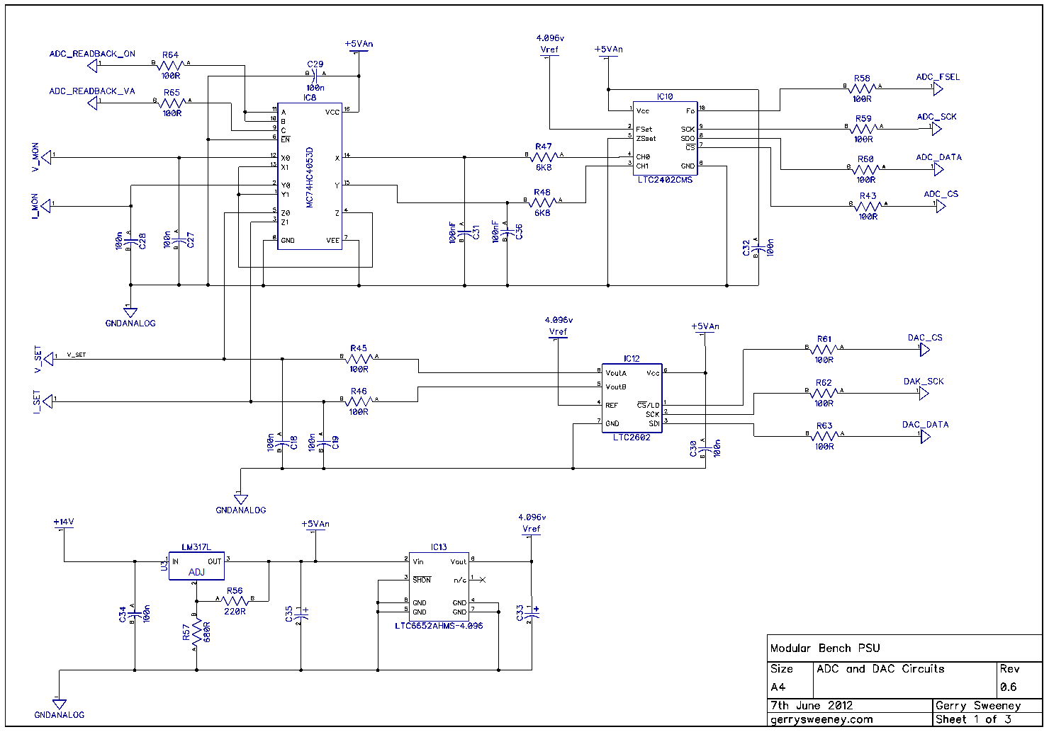
After a fairly disappointing start with the 12-bit DAC from Microchip I have chnaged the DAC to a 16-bit resolution part LTC2602 from Linear Technology. The goal of getting a resolution that is as good as the HP3631A Power Supply means getting a programmable resolution of 1mv for the low voltage range and 10mv for the high voltage range. The circuit below achieves these goals with a high degree of accuracy and no missing codes throughout the range. The design also exceeds the dynamic voltage and current range of the HP shown in the table below. Furthermore I made a statement that I would aim to not only achieve the same resolution but I would also attempt to improve on it by a factor of 10, that means getting a resolution of 100µV on the low voltage range and 1mV on the high voltage range. The 16 bit resolution of the DAC was not quite enough to achieve this, there were missing codes so I used the DAC modulation technique I used for the 12-bit DAC and extended the 16-bit DAC to 18 bits of resolution which allowed me to achieve the ten-fold programming resolution with no missing codes across the entire range – marvellous 🙂

Here is a brief video overview of the modified hardware and test environment

And here is a video demonstration of programming, measuring and the achieved resolution.

I focused some more on noise measurements and found that modulating the output of the 16-bit DAC created no detectable ripple – at least with the test equipment that I have. In fact the noise I am measuring swamps any ripple that is being created now. Interestingly, the digital signals from the micro controller driving the DAC (the SPI bus) is now creating more noise than the ripple effect of switching between two adjacent codes. Because the digital switching does impose some noise, there is a compromise to be had – you can get higher resolution but suffer some additional noise. For low-noise applications you can forego the additional resolution and get better signal to noise performance. Thankfully this can be controlled entirely in software so can be easily made a programmable option which is what I will do.

Of course this is just the control circuitry, I have no idea how the noise or accuracy will be represented through the linear regulator part of the design in practice – we shall see.

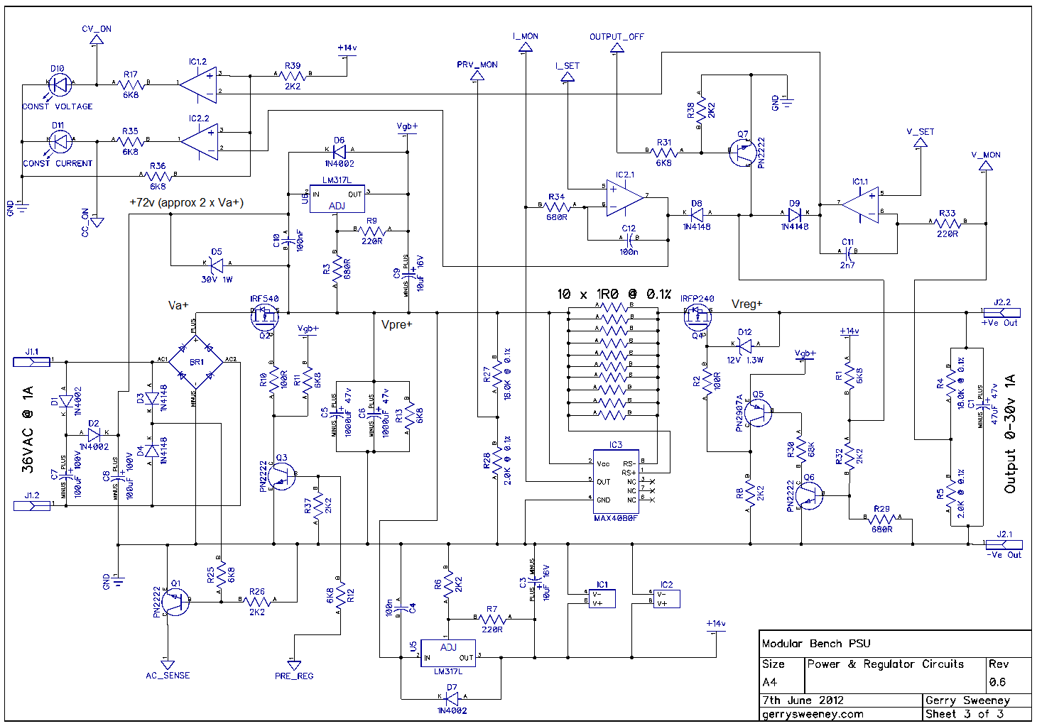
I have broken the schematic into several pages to make it easer to read.


I am happy that the control circuitry and the firmware is now good enough for a Version 1 baseline – this is what we have now. I have increased each range to show the possible extent of each gain option. In the final design the power and voltage ranges required and programmed in the UI/front panel will dictate the actual upper limits of each range, but this table shows the extent of what is possible.

Volt
Range
Volt
Resolution
Volt
Steps
Current
Range
Current
Resolution
Current
Steps
Regulator
Gain
0-8v 1mv/1µV 8000/80000 0-8A 1mA/0.1mA 8000/80000 64W max x2
0-20V 10mV/1mV 2000/20000 0-20A 10mA/1mA 2000/20000 400W max x5
0-40V 10mV/1mV 4000/40000 0-4A 10mA/1mA 4000/40000 160W max x10

In Part 10 I am going to create the first PCB for the project – Whoo-hoo. However, instead of designing the entire PSU printed circuit board at this stage I am going to focus on the digital control circuitry with the ADC, DAC and Analog switch only. I am going to create a small PCB as a module with a simple 0.1″ pin header (Arduino shield style) with the ADC, DAC, Analog switch, PIC micro controller and power supply parts so I can do the first cut of a board layout to make sure the grounding and noise issues are addressed. It’s not my intention to make this part of the final PSU module but it will be a useful module for prototyping other systems and of course I will not waste too much time if I get it totally wrong :/

Catch you next time….
Fully Programmable Modular Bench Power Supply – Part 8

After my initial tests there are two things I now know for sure. The first is I cannot treat the DAC like a programmable voltage source, it’s not going to be accurate enough and secondly, because of the INL of the DAC the resolution needs to be high enough to give me headroom to “trim” the DAC to the correct voltage. On this basis there really are only two practical options to achieve the goal.

The first option is to use a mapping table. Assuming I have a DAC with enough resolution it would be feasible to build some form of calibration rig which could step through each desired voltage then trim the code written to the DAC to get as close as possible for the resolution of the DAC and store that number in a table which can then be written to micro controller as a lookup table. The problem with this approach is its messy, and it would mean that if the calibration was lost in use it would need the calibration rig to re-calibrate it. This is not an ideal solution.

The second option, and the one I will take forward is to build a system where I have an ADC and a DAC and the system is configured so I can read the DAC output. When a given voltage it programmed the ideal DAC code is written to get within a few millivolts of the desired output; and then a software loop is used to trim the DAC code up or down as required to get as close to the required output voltage as possible. If the PSU is to measure up (no pun intended) then it needs a metering function regardless so all I need to do is design the system so I can switch the ADC’s inputs to the DAC for the calibration cycle.

The ADC needs a good resolution, it needs to be accurate and it needs to be low cost. The conversion speed is also important, if its too slow the calibration cycle would take too long to complete. I found a good part for this in the form of the LTC2402 Delta Sigma ADC device from Linear Technologies. I must say at this point that Linear Technologies design support is really great, they have been kind enough to furnish me with sample devices which I have been testing in the design. I have also tested a couple Analog Devices parts too and they were also kind enough to furnish me with sample devices, and these were very close in performance and a bit cheaper too (so not excluded just yet) but for performance in this application Linear Technologies parts so far have the edge – I will talk more about that later on and in future articles because I have tested a few different DAC’s and ADC’s. The following schematic shows the digital control circuitry which is extended to include the ADC chip and a 74HC4053D analogue switch which is used to switch the input of the ADC from monitoring the PSU regulator outputs to monitoring the outputs of the DAC for calibration read-back.

One of the interesting attributes of the ADC chip is it’s a two channel ADC, but in reality though it is actually a single channel ADC with a two channel multiplex on the front end so it samples each channel alternately. This made for an interesting problem to solve because the calibration loop needs the conversions from the ADC to be as fast as possible. The chip its self can only perform a maximum of 6.2 samples per second according to the data sheet, but because of the input multiplexer it can only actually achieve 3.1 samples per second per channel. For normal monitoring three updates per second is acceptable but for calibration I wanted better performance. I configured the analogue switch so in calibration mode I can use both inputs of the ADC to monitor a single channel of the DAC which gives me a calibration loop speed of 6.2 trim and read back per second.

Unlike the DAC, the INL of the ADC is significantly better mainly due to the nature of how it works. The architecture is a switch capacitor system which unlike laser cut resistor strings the charging and discharging of current into a capacitor is significantly more predictable and linear.

https://www.youtube.com/watch?v=f-0m5m7rUQQ
PLEASE NOTE: The LED flash is continuous but the video frame rate make it looks like it stopes and starts – which is does not.

In software I have tired two different calibration schemes. The first is the simplest, it sets the ideal code for the target voltage, measures the output of the DAC and does a calculation to determine the difference between the ideal code and the actual code required, then applies this. The second scheme is more complicated. It is the same as the first scheme but then with a second phase of micro trimming which essentially sets a window around the centre point and then adjusts the codes in steps re-reading the output; you can think of this as an electronic/software version of someone turning a variable resistor while watching a meter to get a precise voltage. The second scheme also takes more time as it needs to perform multiple read-backs in order to complete the trim cycle. I have limited the trim cycle to a maximum of eight iterations, in practice it seems to take between 2 and 7 most of the time.

(P.S. The command ‘pr’ means “property read”, it reads the EEPROM configuration of the module)

I re-tested with the spot voltages in the previous blog post and the bottom line is, 14-bits is not enough. The MCP4922 is great for the $$ but its not good enough for this project so I will not bother creating another spot voltage table for this variation, that’s a waste of time given we have established the DAC is just not up to the job. In the next article I will try out two 16-bit DAC chips, one from Analog Devices and the other from Linear Technology.

Thanks and keep watching….

Microcontroller Source Code