I have been working on various power supply projects of late and was finding that my approach to loading PSU with simple incandescent laps was limiting. What I needed was a programmable DC load so I wondered – build or buy? Because I am already working on a PSU I decided that its probably better to buy one if I can find something that was reasonable quality and at a reasonable price. So I searched around and eventually took a chance on a Maynuo M9711 DC Electronic Load. I had not heard of the company before and could not find much out about them on on the internet, what I did see what that other similar devices that cost twice as much and had a reputable brand (BK Precision for example) were so similar in form that I thought its a good chance that they are different OEM’s of the same design. I am not sure that is the case because I do not have a BK Precision to compare, but I bought the M9711 brand new from the manufacturer on the basis that this was likely the case. Was I disappointed with the purchase? we shall see…
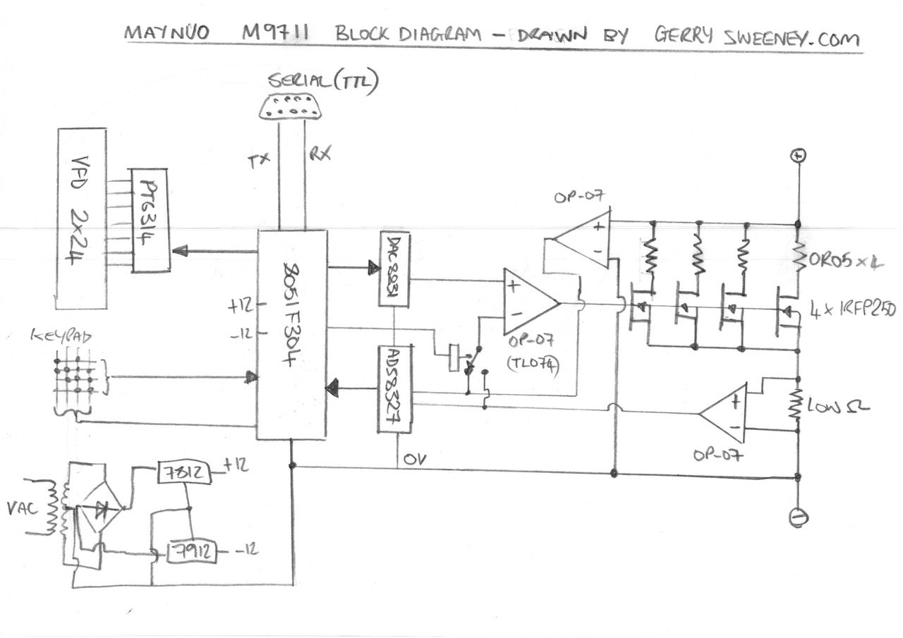
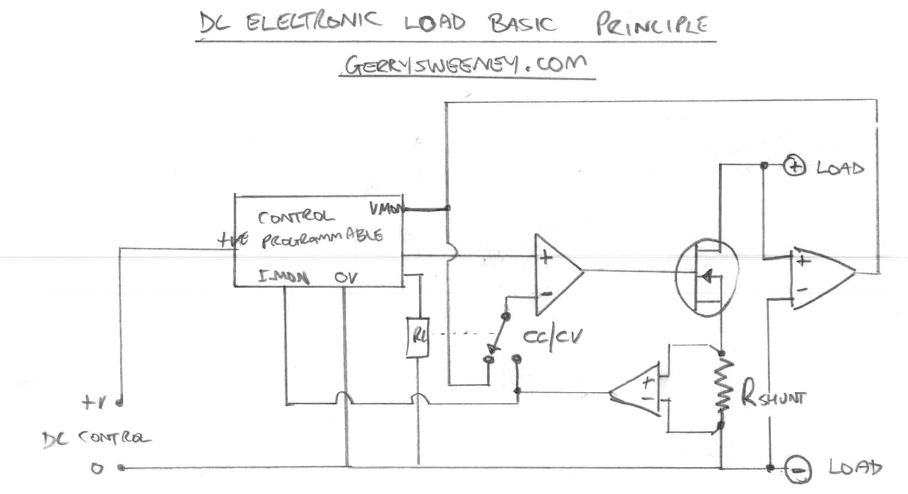
In this video I unbox and then tear down the Maynuo M9711 DC Electronic Load so we can take a look inside and see how it works and how well its been built. I try to explain how a DC electronic load works and I present a block diagram of the Maynuo M9711 based on my understanding and the cornerstone components that I find.
The main funcional components found in the device are:
| Part Numner | Description |
|---|---|
| Silicone Labs C8051F304 | This is an 8051 based 8-bit flash micro controller, this is the main processor for the device |
| Texas Instruments ADS8327 | This is a 16-bit SAR 500Khz Analog to Digital (ADC) voltage output converter, used to measure voltage and current in the load. |
| Texas Instruments DAC8831 | This is a 16-bit Digital to Analog (DAC) converter, used to generate the programmable reference voltage. |
| Princeton Technology Corp. PT6314 | This is a vacuum fluorescent display driver chip |
| International Rectifier IRFP250 | The power MOSFET (x4 in 150W model) used as the main active power device that creates the load load |
Notes and Diagrams
Below are the diagrams I present in the video describing the operation of a DC Load and the basic high-level layout of the M9711. You can browse these images or download a PDF document to print out if you prefer.
Well I hope you find this useful, thank you for reading and watching, catch you next time…
This content is published under the Attribution-Noncommercial-Share Alike 3.0 Unported license.
Attachments
| File | Description | File size | Downloads |
|---|---|---|---|
 MAYNUO M9711 DCLoad Illustration
|
2 MB | 2351 |
The bridge rectifier is used for temperature sensing for the fan control. The TIP41 is the driver for the fan, driven by the LM324.
Hi Mike, thanks very much for the clarification, that makes perfect sense.
A comment was posted on the EEVblog forum in response to my video review which I thought was very relevant so I have re-posted the comment here (with the authors permission). The EEVBlog forum post can be viewed here: http://www.eevblog.com/forum/reviews/maynuo-m9711-programmable-dc-electronic-load-photos/
——
On the question of the current equilizing resistors on the parrallel Mosfets ,yes they are required .I know that because I have just finished designing and building my own so had to find answers to the same problem. The reason for this is that mosfet’s do not have a positve temp coefficient except at high drives (Vgs > 5V) and high currents (Id >20 A for power devices). At these levels then Rds on dominates and this value has a + temp coeff and increases with temp. At a lower Vgs drives and lower currents then Vgs (Th) will dominate and this has a Negative temp coeff and gets lower with increasing temp ,so a small diff in Vgs(th) between two Mosfets of say 0.5 Vgs can cause a difference of 10A Id at the same applied Vgs .
Check out the transfer characteristics of any power mosfet and notice at some piont the Vgs – Id current at different temps will cross over at some ‘inflection’ point from being negative to positve temp coeff.
Check out this short onsemi app note on mosfet temp stability . It will explain better than me
http://www.onsemi.com/pub_link/Collateral/AND8199-D.PDF
Hi Gerry, very interesting teardown. Furrther to the question of the paralleled MOSFET – does the M9711 include a schematic? The current balancing resistors should be in the Source and not the Drain as your diagram shows as they won’t have the desired effect the way you have drawn the schematic. It is OK to parallel MOSFETs directly without “ballast” resistors when used in switch mode if driven well. But linear mode is when the resistors are required.
Here is an another article on the topic:
http://www.microsemi.com/document-portal/doc_download/14700-new-500v-linear-mosfets-for-a-120kw-active-load
The idea shown in this app note is very similar to the HP/Agilent Electronic Load. The schematic for the 6060B is available on the Agilent website. I am curious to know if the M9711 actually uses a separate op amp for each MOSFET.
Thanks for the videos!
Hi Richard, thanks for the correction, you are absolutely right, I should have drawn the resistors in the Source and not the Drain, it was a quick sketch with not too much thought. Unfortunately the M9711 does not have a schematic, nor could I find one. Thanks for the clarification around paralleling MOSFET’s it makes sense although I have seen (obviously not very good) designs for audio power amps where MOSFET’s have been paralleled without ballast resistors, I guess it works when you do nto need to drive the MOSFET anywhere near its inflexion point.
Thanks for the article, I like the idea of driving each MOSFET with its own op-amp and a source resistor for negative feedback, I think if I am to design my own DC load I would take this approach. The Maynuo M9711 does have two TL074’s to drive four MOSFET’s, I did not reverse engineer to that level but given there are eight available op-amps this could well be exactly what they do – it would make sense.
I will check out the schematic for the 6060B, thanks for the comments and info
Gerry
You mentioned that the resistors are 50 milliohms. I would imagine that they are sense resistors. Each MOSFET likely has its own sense feedback and amplifier. In your drawing you show only one low Ohm resistor / OP-07 opamp sense amp, but my guess is each MOSFET has its own sense amp.
Hello Gerry, i was one of the detailed contributors on the eevblog about my own Maynuo M9712B 500V (yikes!) 300W load. I typed quite a lot of STUFF there, so wont repeat it.
You may have already discovered this? If you set VMAX to 20V or lower, and IMAX to 3A or lower, the load drops into much higher resolution displays of voltage and current.
DO NOT be tempted to recalibrate the load! I did, and it took me ages to get it back…
I have a fault with probably the USB serial lead. It is only working one way. How about i sent it to you (with return postage) for you to test out? Not getting much out of Maynuo or the original supplier, now.
Hi Laurence, I think I did see your article I am sure because I recall the recalibrate warning you put out. I did not know about the increased resolution at lower voltages, thats actually a very nice touch, I should have designed something like that into my PSU project, thanks for making me aware. With regret I have too many other commitments to take on any repairs of other peoples equipment. I would suggest trying to figure out what is at fault, the isolator lead or the actual unit. A scope on a DB9 breakout should tell you pretty quickly. I am pretty sue that what is to/from the unit its self is simple TTL level serial, so scope that out and see if you are getting data in/out. If you are its the isolator lead. Gerry
Hi Laurence, sorry, I just re-read your request, you was asking if I would try out your isolator cable on my PSU. Yes I would be happy to do that for you if you want to post it. Please e-mail me (see my contact details in about) and I will send you my postal address. I cannot guarantee a fast turn-around but I will certainly try it out for you. Gerry
Very useful Video Gerry. I am also building an electronic load using 60A Mosfets. The teardown and details on how it works was very useful.
Kaushlesh
Glad you have found it useful, thank you for watching and good luck with the build.
I ordered M9712, after watching your video teardown
Thank’s for explanation how it works (even i did not fully understand)
La Ode
You are welcome, I am glad you found the teardown useful. I have been using the load a fair bit now and so far its proven to be very useful and very reliable. Gerry
Hi Gerry. Thank you for the teardown. After doing some research for commercial programmable loads, it seems like Itech Electronics (http://www.itech.sh/en) is at least a supplier to BK-Precision, Maynuo and other companies. Itech also sells rackmount power supplies that BK does not offer so it seems that Itech is not a division of BK as much as a vendor. Itech’s web site implies it is a BK company. Don’t know for sure.
I’m looking to purchase the M9715B or M9716B depending on quotes that come back from my buyer in China. The “B” is the 500V grade product, both support a max of 120A and the 9715/9716 will dissipate 1800W/2400W respectively. I expect my teardown of one of these will be very similar to the M9711 but with additional parallel MOSFET stages and heavier shunts, etc. My job involves designing and testing power supplies and the 150W unit would suffice for most projects but I also want to test and grade solar panels, inverters and storage batteries.
Itech will soon release a single phase AC load with DC load capabilities – the best of both worlds. My future applications will involve developing 208V/3-phase sine wave inverters so the Itech AC load will not be of too much help. I can manage to do quite a bit of development with a larger DC load that is available now.
I am curious how Itech will design the AC load. For single phase use, it would simply be a bipolar DC load with the neutral at 0V and the hot line swinging 169V p-p about the neutral. To develop a 3-phase load, there are phase-phase currents, both imaginary and real and WYE & delta voltage setups. When I get time I may try to sketch out the load circuitry of a 3-ph electronic load. Off the top of my head there would be (3) phase-phase current shunts but I still need to think about bipolar (below 0V) operation.
I did quite a bit of research in developing electronic loads and am a bit disappointed about the lack of voltage isolation between the load and controls in the Itech product line. I plan to use 2kV high speed opto-isolation between the microcontroller and A/D & D/A converters. This way all USB & serial communications will be grounded with respect to line voltages to safely connect to PCs and the analog side with be floating with the hot load. Most of the sigma-delta converters are SPI based and should work with sufficiently fast opto-isolators.
I look forward to receiving my programmable load, all 32kg of it.
Dennis
Hi Dennis,
That sounds like a monster of a load. From what I can tell there is one man behind the design of the BK/Maynou/Itech products, I am not sure which organisation he represents but they all sure seem to be linked in some way.
I imagine an AC load would work much like a DC load with a bridge rectifier on the input terminals (in simple terms), it should not be too hard to make a load responsive to AC currents, and if you think about it that would explain why the AC load has DC capability.
Gerry
Hi Gerry,
My price for the Maynou M9715B and M9716B are $1550USD and $2350USD respectively so I think I’ll go with the M9715B 1800W unit. It seems like a lot of capability until you put it in terms of a practical load like 5.3A at 339Vdc (rectified & filtered P-P voltage for 240VAC input supplies). This can be used for testing of PFC front ends, etc.
In comparison the list price for the BK-Precision 2400W 500Vdc unit is $6975USD so I don’t feel too bad about paying Maynou’s prices being about 1/3 of BK’s prices.
My buyer in China is packaging a pallet of materials for me this week so I thought it would be a good time to add an electronic load to the shipment. I made sure to specify 120Vac operation for use in the US. I’ll post a link to my teardown when I get it. I’m curious how they handle 500Vdc inside the box in terms of increased clearances.
Dennis
Hi Dennis,
Thats a big beast of a DC load, let me know how you get on with it.
Gerry
Hi, this is Kate Zhou from Maynuo Electronic. Thanks for all the comments on our products.
Maynuo offers M97 series DC electronic loads from 150W to 200KW and DC power supplies from 150W to 1200W.
Hello Gerry
I thought that was a very interesting and comprehensive video.
We are authorized UK/Ireland distributors for Maynou Electronics.
Thank you. Best wishes for a lovely Christmas!
Joy Torres
Hi Joy,
Thanks for your feedback/comments
Gerry
Thanks for this – very useful and the only circuit of any kind I’ve found. I’m looking because I seem to have blown up my M9711, possibly by inadvertent reverse voltage application. I’m trying to work out what is likely to be damaged but have no experience of MOSFETs (not covered when I went to uni!). Symptom is no current drawn in normal polarity, and near short circuit in reverse polarity. Power-on self-test is ok. I assume I’ve blown the MOSFETS and will probably just replace them and hope. Would you have any thoughts on this?
Hi Julian,
I would suggest based on what you describe that your input protection is working OK, its a diode basically so reverse polarity the diode is kicking in, so its unlikely that you damaged it with reverse polarity otherwise that diode would be either a short because that diode you are seeing would be either short circuit or blown apart. MOSFET’s most generally fail short circuit so just replacing them will most likely be a waste of money. I would be inclined to open it up and get your multimeter out, the circuit is quite simple. A MOSFET is nothing to be afraid of, think of it as a voltage controlled transistor, the more volts you apply to the gate/source (up to about 10v or so) then the more it will conduct current drain/source – in this circuit you can simply think of it as a voltage-controlled low value resistor, very similar conceptually to a valve (vacuum tube). Hope that helps.
Gerry
Thanks Gerry. I have received a response from Maynuo, they gave me some useful advice so I’m pleased with their service. Embarrassingly, it all turns out to be finger trouble, combined with not knowing about the reverse body-diode in the MOSFET and a couple of other contributing factors. The only think I had to fix was a loose fuse (external to device). You’ve probably lost interest in this topic by now, but I can confirm that the device uses one op amp per mosfet.
Overall it’s a great piece of kit, I love it, though I can sympathise with your correspondent above who had to calibrate his.
Incidentally I’m pretty well up on MOSFETS now, your comparison with valves is ancient but illuminating. Thanks again for the video, it was a great introduction giving me confidence to pull mine apart. Impressed with the construction too – a model of elegant sufficiency.
Cheers
Julian
Hi Julian,
Glad you got it sorted in the end. I have to say that company does seem quite responsive and helpful. Glad the MOSFET explanation was of some help
Gerry
is there a reason to not put some snuber on the mofset in the dc electronic load?
i believe i understand how it work, you need to evacuate the heat from the Ton period trough the mofset and the ballast
but the heat from the switiching time is not wanted (, isn’t it?)
my bad, there is a diode in the mofset, but is it enough?
I do not recommend buying this DC load. I bought a Maynuo M9712C and it has a problem measuring voltage while discharging a current higher than 20 amperes. Here is a video showing the problem: https://youtu.be/ABcOg52YfbY
The worst part is that the company is unable to give any assistance or take any responsability about this issue.
Thanks for your comments/post
Hi Gerry,
your tear-down video well explained everything about electronic load.
I have few question on that.
1. How bridge rectifier used as temperature sensor?
2.Why mosfet driving op-amp tl084 need negative 12V power supply? i think without negative voltage it will work as same…
1. Uses the silicone diode junction which has a negative temperature coefficient.
2. To be able to get to absolute zero volts, and not just above zero.
Gerry
Hi Gerry,
Wow, its been 6 years since your original post. Wonder if the loads have changed much.
Any idea how the Maynuo decides on overpower. Will it take a little over the rated for a few seconds? Specifically, I’d like to use a 300W load (M9712B30) to make MPPT curves for a 325W solar panel. So it might see 325W for a long enough pulse to get a stable reading, 10s of milliseconds? then a long pause then a slightly different current pulse ect. ect.
Mike
I think it will probably handle the small overload ok, but depending on the mode it might limit the power and not actually draw the full 325W
Gerry
Hi everyone, I’m Marco, I have a problem with M9712B30 500v 300W, can you help me?
A 14D201K varistor is mounted on the instrument input in position Y3 in parallel with the input, as the instrument goes up to 500v it appears to have been mounted incorrectly at the factory.
While a 14D751K varistor is mounted in position Y1 which is connected between positive input and ground, is it possible that they were reversed at the time of assembly?
if you have this tool can you check how yours has been assembled?
Thanks.
Hi Gerry. Could you place the circuit maynuo M9711. Thanks for the answer
Hi, I am afraid I do not have the schematic for it
Gerry