So I present the third in what is starting to feel like a long line of Agilent PSU repairs, but before you read on you should know that I have now depleted my collection of broken Agilent E36xx series power supplies so I will need to find another subject to blog about next time! That being said, even though I have blogged about two other PSU;s from the same family, I thought it would be worth videoing the repair exercise and at the same time try to demonstrate how I go about identifying and resolving a fault on this kind of circuit. The E3646A is a different model to the other two PSU’s I have repaired and blogged about – this one is a dual output 0-8v @ 5A / 0-20V @ 2.5A for each channel and the internals are different so I hope this will be of some use for anyone who may need to repair one of these.
Notes and Schematic Parts

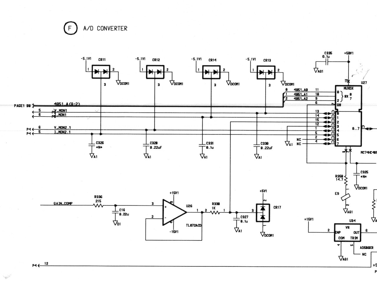


You can download the Agilent E364xA Service Manual which include the schematics
I hope you find this useful or interesting. If you do please give the video a thumbs up and if you have any comments or suggestions please post them here and I will do my best to answer them.
Thanks for watching and catch you next time.
This content is published under the Attribution-Noncommercial-Share Alike 3.0 Unported license.
Attachments
| File | Description | File size | Downloads |
|---|---|---|---|
 Agilent E364xA Service Manual
|
|
7 MB | 4854 |
Very interesting, great diagnosis and troubleshooting
Thanks Evan, and thanks for watching
Did you look under the microscope at the faulty resistor? I cant remember if you said or not.
Haha, thats a funny question, I lost the bloody thing, I did not vacuum yet so I might still be able to.. 🙂
Just curious lol
Actually, I just found it and had a look, it definitely does not look damaged so is a simple component failure. Unusual but there we have it.
I just came across your videos and enjoy them very much. Could you say a few words, or perhaps include a video some time, about your equipment and methods for replacing smt components on boards like the Agilent power supply?
Hi Robert, you can see a (not very verbose) list of my test equipment here: http://gerrysweeney.com/my-gear/, I am not sure I will get around to doing a video on SMT soldering, there are many such video’s, there is a good tutorial series done by Dave Jones of the EEVBlog thats well worth checking out: EEVBlog Soldering Tutorial. Gerry
Hi Gerry,
Can you give me some pointers as to where to look when both outputs slam to 31V? The readouts are ok with no appreciable current. I also examined the board and could not find any signs of burn marks. What’s frustrating is once I pull the bottom board out, I can’t really get all the connectors back on to test it since they are all so short, and I would need many extensions which I don’t have.
Thanks in advance,
Richard
Hi Richard,
Yeah I had to make up longer cables to work on the PSU when I fixed mine. If both outputs are slammed to the rails you might want to check the output transistors for short circuit collector-emitter. Other than that simple fix you will need to get the meter out I am afraid, if its not the output devices then it could be pretty much anything.
Gerry
Just wanted to say thanks for posting this video. It gave me some ideas around doing some investigative work around my HP supply.
I commented on your video too, but thought I would post here too.
My voltage is sagging, slowly at first, and then quickly, and then it resets back to a value close to the set value, and then repeats. It is a bit intermittent. The video below shows 2 occurrences of the issue. Channel 2 is fine – only channel 1 seems to be effected. If you have any ideas on where to start I would love to hear them. (I haven’t even opened it up yet, since I just discovered the issue yesterday.)
https://www.youtube.com/watch?v=DB50e-rGM6g
That does not look like the sort of noise I would expect that PSU to generate, you might want to check other sources of noise in yiour environment, LED lights are a good candidate for that sort of bursty noise.
Gerry
Hello Gerry,
well, I find your information that you have a scematic and circuit diagram of the E3648A Agilent PSU.
So I’m look for this papaers.
Is there a way that you send me this by PDF ??
BR
Gerald
Hi,
There is a link to the service manual which includes schematics on this page
Gerry