HP 339A Teardown

A piece of equipment I use rarely but when I do I find really useful is my HP 339A Distortion Measurement Set. Built in the 70’s this unit has a precision sine wave oscillator and distortion measurement section. One of the things thats really nice is the oscillator and the notch filter are tied together and the notch filter auto-nulls to make measurements really easy to accomplish.

The build quality of this unit is impeccable, made by HP when they were making stuff properly. The entire chassis is made from folded high quality aluminium sheets with capture nuts and really precise machining. The main oscillator switches are coupled using a bar and wafer scheme but both the oscillator and the filter are fully screened and isolated in their own chassis sub-sections. The smell from inside the unit is that old-school electronics smell I used to encounter all the time when I was a kid taking apart old TV’s and Record Players. I don’t know what chemicals exactly make that smell but I am pretty sure if you could bottle it you could sell it – there is an idea for a unique aftershave! It could be called “Ye’old TV Man”!

Anyway, hope you will find the video interesting. Thanks for watching.
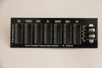
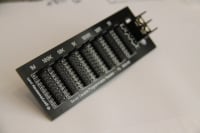
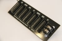
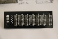
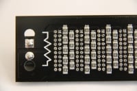
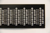
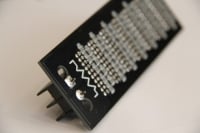
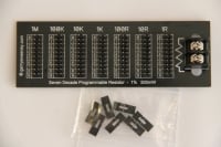
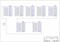
Seven Decade Programmable Resistor – A Low Cost Solution

I have spent a lot of time over the years prototyping electronic circuits and the amount of resistors that have ended up in the trash because they are so cheap you don’t bother to keep them tidy or organised once you take them out of their organised storage – you know the story. One potential solution to this is a programmable resistance box but the problem with these things are they are bulky and expensive and do not lend themselves well to breadboard prototyping. The cost of construction means they are typically the reserve of high-precision resistance boxes. I have a CROPICO RBB6E resistance box in my lab which I open up to have a look inside, its really well made, mostly by hand too, far too nice to abuse in prototyping….

I looked around at what is available but did not find a solution that met my own requirements so I decided to design something simple myself. I also wanted to make a simple project to get manufactured by machine which apart from other things requires reasonable volume, and I thought this project would be useful enough to others that I should get some made and make them available.

Various Pictures

IMG_5847.JPG
IMG_5847.JPG
IMG_5850.JPG
IMG_5850.JPG
IMG_5851.JPG
IMG_5851.JPG
IMG_5852.JPG
IMG_5852.JPG
IMG_5853.JPG
IMG_5853.JPG
IMG_5854.JPG
IMG_5854.JPG
IMG_5856.JPG
IMG_5856.JPG
IMG_5858.JPG
IMG_5858.JPG
00000273.png
00000273.png

Project Discussions

Project discussion thread on EEVBlog forums

Other Resources I mention in the Video

Cheap Resistance Substitution Box by @vtl on the EEVBlog
Cheap Resistance Substitution Box – Hack-a-day

If you do want one of these I have these for sale on “tindie.com”, the item listing is here:

https://www.tindie.com/products/gerrysweeney/seven-decade-programmable-resistor-1r-9999999r-1-500mw-gerrysweeneycom/

I have also listed these on e-bay, you can search for “gerrysweeney.com” which will find the listing.

As ever, if you have any comments, suggestions or feedback, please use the form at bottom of this page

Thanks for watching

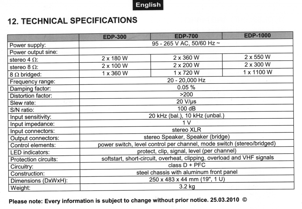
Omnitronic EDP 1000 Watt Class D Amplifier Teardown

Here I describe the basic operation and topology of a Class D amplifier and then tear down an Omnitronic 1000W amplifier to have a look and see what is inside. The big advantage of a Class D amplifier is the compactness and overall power efficiency. However, Class D amps are generally not used in High Fidelity application because of the limitations in dynamic range and distortion performance that can be achieved.

Here are the specifications scanned in from the user manual.

Hope the information is of some use. Thank you for watching.

HP 53131A Frequency Counter Teardown and Spillage Clean-Up

One of the instruments I have is a HP 53131A Frequency Counter, and putting the positives of this unit aside, its by far the most annoying bit of test gear I have! Why? well for some reason, when you apply power to the thing the fan runs even when its switched off. This is because the power switch is a soft switch and with just the AC cord plugged in the fan runs and makes the annoying fan noise. This is a really poor design and certainly not one of HP’s shining examples of engineering….I like to be able to switch my stuff off without reaching around the back and having to pull the power chord or unplug from the wall outlet – just plain crappy! HP what where you thinking?

I thought I would tear it down and have a look and see why this is, and perhaps see if there is any possible modification I could come up with to improve on this. When I took it apart I found a real mess of dust and some kind of substance spillage so a full clean-up was needed which somewhat distracted me from the power switch problem.

While its in bits, I also do a quick run through of the major components of the circuit and have a quick look at the power supply and power switch circuits in some detail.

UPDATE: The clean-up also appears to have resolved the strange trigger problems I had seen previously with this counter. Well pleased…

Here is the Agilent 53131A Component Level Manual including schematics for the frequency counter

Thanks for watching…

My E3634A Mystery Explosion – WTF!

This is a short follow-up to a video where I was recently testing a Mayyuo M9711 DC Electronic Load (See Here) and I was using an Agilent E3634A Power Supply (which I previously fixed) as a power source. When I put the DC load into pulse mode within a few seconds the E3634A PSU exploded. What I heard was a loud pop, and a flash followed by a loud vibrating 50Hz hum, by which time I was able to reach the power switch and shut it down. I switched to another supply and continued with the test of the M9711 but today I thought I would open up (once agin) the E3634A and see what damage was done and what I found is a real mystery!

Did I imagine it all? Was there beer involved? Who knows, its a mystery!

Hope you enjoyed the video, catch you next time…

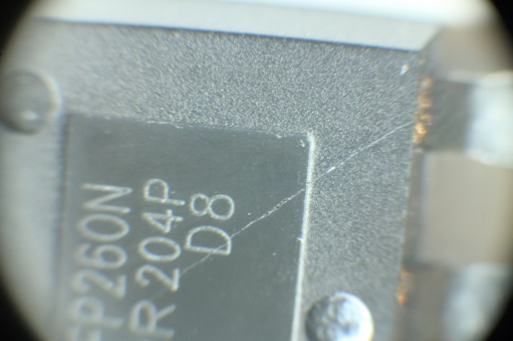
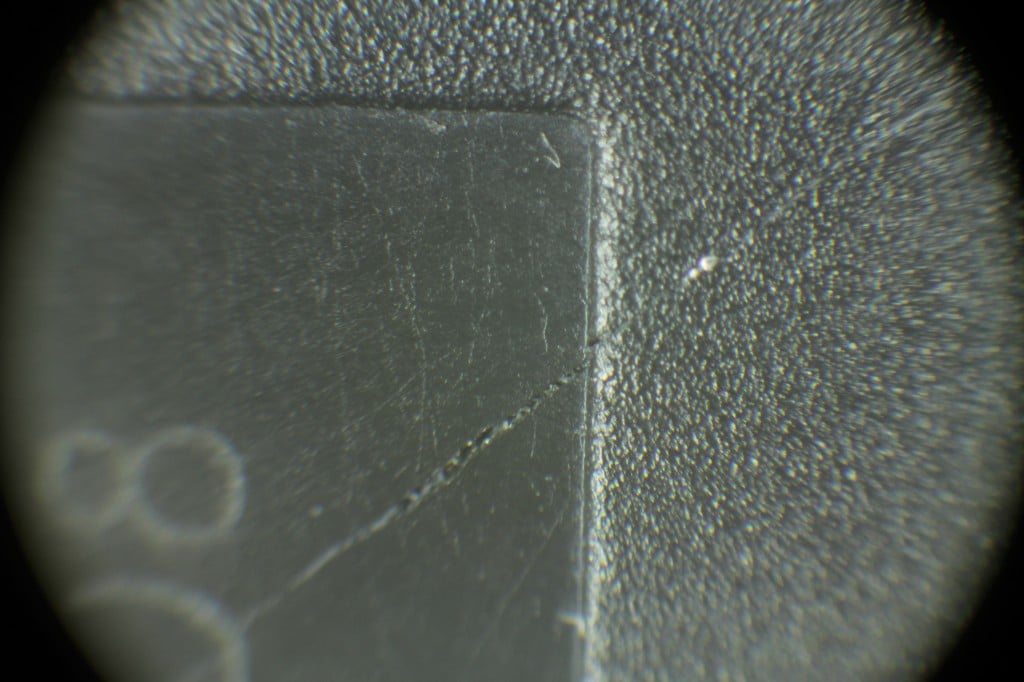
UPDATE – I found the smoke source

While tidying up I thought i would have a look at the two power MOSFET’s that failed and found the IRFP260 has a very small but visible smoke vent! I have added the photo’s below, I had to take these under the microscope x10 and x30 to see it. With the naked eye it looks like a light scratch.

Maynuo M9711 DC Electronic Load – Unboxing, Teardown and Quick Test

I have been working on various power supply projects of late and was finding that my approach to loading PSU with simple incandescent laps was limiting. What I needed was a programmable DC load so I wondered – build or buy? Because I am already working on a PSU I decided that its probably better to buy one if I can find something that was reasonable quality and at a reasonable price. So I searched around and eventually took a chance on a Maynuo M9711 DC Electronic Load. I had not heard of the company before and could not find much out about them on on the internet, what I did see what that other similar devices that cost twice as much and had a reputable brand (BK Precision for example) were so similar in form that I thought its a good chance that they are different OEM’s of the same design. I am not sure that is the case because I do not have a BK Precision to compare, but I bought the M9711 brand new from the manufacturer on the basis that this was likely the case. Was I disappointed with the purchase? we shall see…

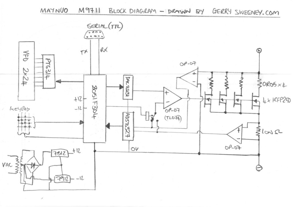
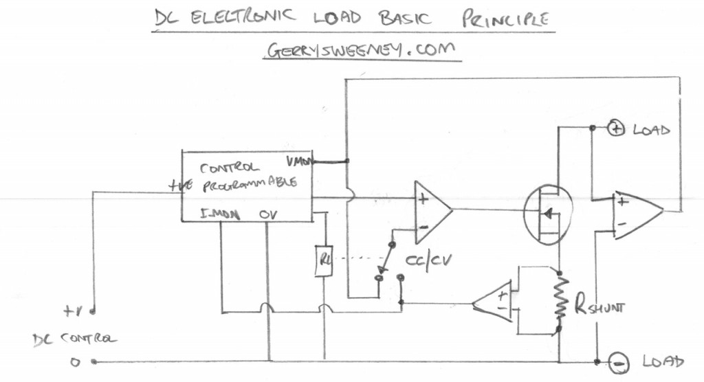
In this video I unbox and then tear down the Maynuo M9711 DC Electronic Load so we can take a look inside and see how it works and how well its been built. I try to explain how a DC electronic load works and I present a block diagram of the Maynuo M9711 based on my understanding and the cornerstone components that I find.

The main funcional components found in the device are:

Part Numner Description
Silicone Labs C8051F304 This is an 8051 based 8-bit flash micro controller, this is the main processor for the device
Texas Instruments ADS8327 This is a 16-bit SAR 500Khz Analog to Digital (ADC) voltage output converter, used to measure voltage and current in the load.
Texas Instruments DAC8831 This is a 16-bit Digital to Analog (DAC) converter, used to generate the programmable reference voltage.
Princeton Technology Corp. PT6314 This is a vacuum fluorescent display driver chip
International Rectifier IRFP250 The power MOSFET (x4 in 150W model) used as the main active power device that creates the load load

Notes and Diagrams

Below are the diagrams I present in the video describing the operation of a DC Load and the basic high-level layout of the M9711. You can browse these images or download a PDF document to print out if you prefer.


Well I hope you find this useful, thank you for reading and watching, catch you next time…