Over a year ago now I repaired a HP/Agilent E3631A triple output PSU and have been using it very often ever since. Recently I bought an Agilent E3634A PSU which is a single output but high power supply, I bought it in non-working condition for not very much money (about $90). It turned out to be a non-trivial task, with physically burned out components and a difficult to track down and understand secondary problem. The components to repair the supply cost less that $20 and the repair exercise was challenging and educational so well worth the effort.
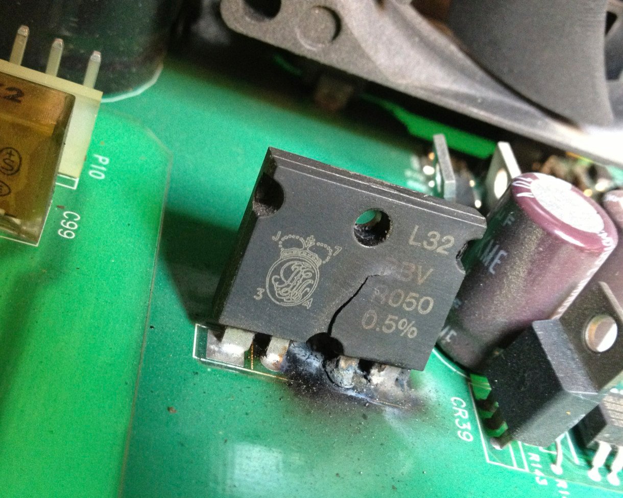
SMOKIN’ HOT…..
I decided that for this repair I would try doing a video teardown and repair which I have not done before. The repair took quite a few hours in the end, although I carried out the repair over about 4 weeks elapsed.
This is a really useful addition to my work bench, the high power nature of this supply makes it very useful for working in low voltage systems like audio amplifiers communications equipment and automotive applications that have high power requirements.
The Agilent E3634A Service Manual with schematics is available on the internet for download, I have provided a link here for convenience.
See you next time…
This content is published under the Attribution-Noncommercial-Share Alike 3.0 Unported license.
Attachments
| File | Description | File size | Downloads |
|---|---|---|---|
 Agilent E3634A Service Manual
|
4 MB | 22492 |
Just posted this to the eevblog forum:
http://www.eevblog.com/forum/testgear/agilent-e3634a-power-supply-teardown-repair/
Interesting video!
Any chance of another installment of the power supply design soon?
Hi, I am working on the next installation. Thanks for the comments
hello gerry, is a former coach of motorola, I have a e3634a and introduces me the following problem: the display shows unreg, the indicator shows [-0.5 volts] and [amps 0.9], I already changed upon the two IRFP260N that They were short, if I perform the test, it is PASS – NO ERROR.
Could you tell me where I could begin to understand the fault where it originates? in thank you,
I extend cordial greetings from Naples – Italy.
Hi Francesco,
These are complicated PSU’s, the only way to figure out what is wrong is to get the schematic and your meter and start making measurements. A shorted pass FET probably means there is some other problem in the regulator loop but it would be impossible to say what without measuring and testing. Good luck with it though, if you like fixing stuff they are interesting and good fun to learn about.
Gerry
Fantastic, exactly what I needed.
I’ve got an E3633 with the same issue; Display maxing out on both amps and voltage and the actualy voltage output is very high.
I got not physical marks tho as your burnt shunt, but I started measuring that shunt like you did and to my suprise I measured ~200kohm between the two outer legs.
I then measured the IRFP064 (Q5 linear regulator). 0.02 ohms between source and drain. 3 ohms between gate and drain/source. Q6 seems fine tho.
Also, the 33 ohm resistor was burnt out just like yours.
Do you think some other ciruitry in my psu is worth replacing aswell?
I’ll definitely keep an eye on your blog from now on. 😛
Hi, I am not sure bout the E3633A model – it looks very similar to the E3634A so thats good. If your shunt resistor is open circuit, look at the schematic and replace (or at least remove and test) any op amp directly connected to the shunt resistor as it will likely be dead. The two in question is U44 which is an OP-07, and U43 which is an AD706. Both parts are easily available from mouser or farnell. Let me know if you manage to find the original shunt, I could not, although my alternative works very well. Looks like this could be a common fault on these. Good luck with the repair. Gerry
Thanks for your response. The shunt on the E3633 is slightly different compared to the E3634. Mine is a 0.01ohm 10W one, compared to 0.05ohm 3W on yours. I found the shunt for E3633 on Elfa Distrelec
https://www.elfa.se/elfa3~tr_en/elfa/init.do?item=60-575-44&toc=20042
Tho this one is 1%, while the original one is 0.5%. Dyu think it’ll make a noticeable difference?
Will check out those opamps aswell.
Thanks very much for the link, thats really very helpful – I was not aware of this company and they look like they have very good stock of the precision power resistors. They even have one reasonably priced 0.05R that might be just the job for my own PSU project :). In terms of the resistor tolerance – I don’t think it will make too much of a difference, it may technically put the PSU very slightly out of spec but I doubt it would be an issue in real life – the part you have identified has pretty decent temperature coefficient at 30ppm, if it were me I would be more than happy with a 1% resistor in there – the calibration routines in the firmware will take care of the rest I think.
Hmm, so I finally got around and changed those parts (OP-07 and AD706). I didnt get my hands on that shunt so I did the same bodge as you, and still its something wrong with the power supply.
Output is giving 0.2587v regardless of output state. Display is showing -0.014V and 0.055A, and I’m not able to change that.
http://imgur.com/NUoG6NX
http://imgur.com/pjV8Fdi
Dyu have any idea of what’s wrong with this sucker or where I should look?
Sorry to hear that. It would not be easy to guess what might be wrong, you need to grab the schematic and work your way through it with your meter and a scope. Start with making sure the reference voltages are being generated as you adjust the voltage current settings then work your way through the schematic. Being basically a closed loop DC servo, everything has to work, once I had a basic understanding of how the thing works i started isolating parts of the circuit by removing key components and injecting DC in to help verify each part was doing what it was supposed to do. Good luck.
Unfortantly I can’t adjust votlage and current settings, but after some probing around it seems that the -15V rail is missing which also means the -5.1V rails is gone. Which is odd because I thought I’ve already checked all power rails, apparantly not. Seems like the zener on the -17.4v rail is ruined, because the -17.4v is present.
The -15V rail is powering various opamps and other circuitry related to the adc. Same with the -5.1V rail which is connected to the I_MON and V_MON through some BAV99 diodes. Not quite sure why its done like that? So I guess I’ll get that zener replaced for starters. Quite nice troubleshootingtraining this power supply. 😛 The schematics are a major pain tho.
Unfortantly I dont have a second power supply so I can’t inject voltages. 🙁
That will almost certainly be why you are seeing what you are seeing. The zener is about 2.4V – you get about 0.6V forward drop across a normal silicone diode, if you do not have a zener to hand you could put four diodes in series and tac it onto the board to prove the problem. I do not believe the voltage is that critical. The schematics are horrible to read for sure, they take some getting used to. Gerry
Well what dyu know. Replaced that zener and the output is now working. Voltage is pretty much spot on but the current is ~50mA off compared to what I set the limits to. Measured with my Fluke 289. Only problem I now have, is that the readback dosent work. I can turn the knob to increase the voltage but the readback is not changing; showing the same as before. http://imgur.com/pjV8Fdi
Any suggenstions?
Hi, glad you are making progress. It would be hard to guess, you need to get the scope and meter out. Your starting point is U24 which is a 74HC4051, this is the input MUX for the ADC circuit. All read back voltages go into this chip so thats a good point to isolate and test. It might be as simple as replacing the 4051 but it often is not, have a look at the schematic on the page where this chip is shown, all around there could be suspect. Good luck.
Hi, ye I’ve already replaced the mux without any changes. Tho U28 (one of the OP27) was broken. I swapped it and bingo! I got measurements on the display again. It was slightly off so I just did a quick Voltage and OVP calibration with my Fluke 289 and its back on track. Current measurement is still 50mA off but I dont have the required equipment to calibrate the current part, unfortantly. Any suggestions on that part? Dyu think Dave Jones dummy load would do?
Thanks alot mate. Really happy I managed to fix it.
Glad it worked out for you. I have not yet gotten around to calibrating mine either, Agilent recommend a reference resistor. I have a programmable DC load made by Maynuo which I recon would work, I need to get around to calibrating my own PSU’s. What ever you use needs to be calibrated though. Not sure about the Dave Jones load, I have not looked at it. Gerry
Hi Gerry,
Do you have the service manual w/ schematics? I found one in our recycling pile at work (Do not use) which I’d like attempt to fix… I don’t yet know what’s wrong with it…
Maurice
Hi Maurice,
I have updated the related blog page and added a download link to the manual. The link to the blog page is in the first line of the video description. Good luck with the repair.
Gerry
Dear Sir
I have one HP Agilent E3632A with some error
All information i description in topic
http://www.eevblog.com/forum/repair/help-me-repair-hp-3632/
Hope you help me to repair HP E3632A
Big thank you !
Nam Nguyen Hai
Dear Sir
I copy all informantion in here
I have one HP E3262 and 3 pcb in good condition (no broken – no blow IC )
But :
– 1 PCB Mainboard have Error 625 ( Communication with GPIB and RS 232 ) , Turn on display work ok but when i rotatry encoder for change voltage and current. Any thing not change.
Voltage display in 0.0xxx V ( like reference voltage )
– 1 PCB have Unreg , when power on , only CV display , don’t have CC . Everything ok ( Not have error like 625 – I/O Communication Error)
– 2 PCB when power on have long beep . Beep ..beep in 2 second . Display won’t work
– 1 PCB brokent input but we have any part in good condition to replace for Error PCB
Pls help me to repair and guide to me how to step by step check and fix it.
Below it’s link for download HP 3632 Service Manual
https://drive.google.com/file/d/0Bz4cInwDnxUlREo5cFQxWTBTUEU/edit?usp=sharing
or
http://w140.com/sbcman/Technical%20Manuals-Main/HP/Power/Service/E3632ser.pdf
Sorry for my English , help you understand ( I live in Vietnam)
Many thank you so much !
My contact : [email protected]
Best regards
Nam Nguyen Hai
Thank you for this blog..
In my supply both Q5 & Q6 were IRFP150.
In the service guide Agilent refer to IRFP064 and IRFP260N for Q5 & Q6 so I guess that it’s not that critical what FET you use…
I dont think the FET’s are that critical no, so long as they are in the right ballpark they will do the job just fine. Gerry
1128/5000
Hello
I already have a working E3633A was damaged Q5.
However, I have repeatedly calibrated the current, I still have an offset when measuring the current. 13mA just like you in the 45:58 movie.
The -13mA current is generated from the current source R147 and Q7. To remove this incorrect indication I even gave a 20k potentiometer to compensate for the offset on the U44 system between pins 1 and 8 (Vos trim) and 7 – it is responsible for measuring the current on the display. In this case, the current measurement is the same as on an external amerometer, but the CC setting is error-free twice and has 26mA at zero output current.
However, the calibration procedure level the settings on the potentiometer and again there is 13mA on the display. So calibration “works” because it removes the offset caused by the potentiometer, which appears on U44.
After calibration the CC settings and current measurement are the same, however, they have a 13mA error. When the CC current decreases below 13mA, the output current begins to flow in the opposite direction from the Q7 current source and the voltage is -0.4V negative. When setting CC to 0.001mA the current flowing to the output is -12mA. Maybe someone knows where the problem is.
Michal