As part of the Fully Programmable Modular Bench Power Supply project I needed to measure the temperature of the heat sink in order to provide some thermal protection. The aim is simple enough, monitor the temperature of the heat sink and if it gets too hot shut it down until the temperature returns to an acceptable level. As it turns out there is more to this than one might think.
Firstly I needed to decide on a sensing device. There are numerous options to choose from falling into three main categories of passive, active linear and active digital.
Passive devices like RTD’s and Thermister’s are available in all sorts of types and are basically resistors that change value with temperature. These devices need circuitry around them and can be complicated to use mainly because their rate of change is expressed as a percentage per degree which in practice means a very non-linear response curve to temperature change. For my needs this was too complicated, at best I would need some kind of signal conditioning, feed into the micro controlled ADC and a software map of temperature vs. voltage to get a reading.
Digital devices such at the Dallas DS1821 can be connected to a micro-controller or in the case of the DS1821 a 1-wire serial bus. The device can be queried and it will return information about the current temperature it is sensing. These are very nice all digital devices but carry the penalty of cost, they are not cheap, costing upwards of $2 a piece. Because of cost I decided not to pursue the use of these
Analog devices are solid state devices that provide a variable voltage out that directly relates to temperature being sensed and are basically linear. These devices are typically low cost, simple three pin devices with power in, ground and volts out. The following are good devices to look at: –
I was thinking about the Bill of Materials for my project and was not really wanting to add yet another part. I had read somewhere that silicone has a very linear temperature co-efficient of around -2mV/°C of temperature change, which means if you measure the voltage drop across a diode or transistor junction you will see a 2mv decrease in voltage dropped for every degree of temperature rise. As my circuit was already using some PN2222 devices which are general purpose NPN transistors and LM358‘s I thought it would be an interesting exercise to see if a simple discrete temperature sensor could be built.
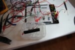
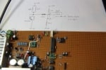
Pen, paper, breadboard, some bits and an hour yielded the following circuit:
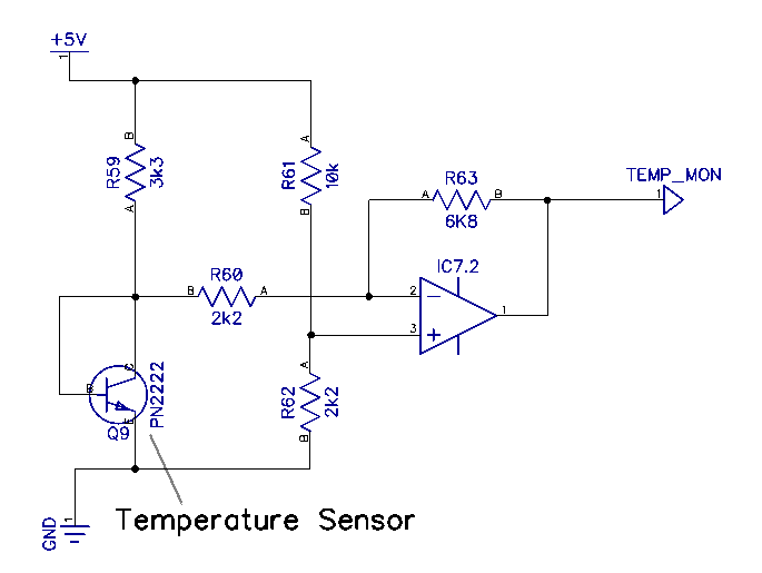
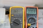
This circuit provides a voltage swing of +1.5v to +3.5v for a temperature range of -50°C to +150°C. I was only able to test it down to a few degrees below zero but it tracked all the way up to 150°C without any problems. The data sheet for the PN2222 states it will operate down to -50°C so I have no doubt it will track downwards. Room temperature was at around 2v, I used a type K thermocouple and a Fluke 289 meter to calibrate it. The results of this circuit are surprisingly good and I did not add one single item to the BOM on the project, every component was already in use elsewhere in the circuit.
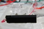

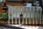
Unfortunately the problem came when I needed to couple the device thermally. The main heat generating device on the project in question is an IRF540 in a TO-220 package. Bonding the PN2222 to the heat sink close to the device was my plan but in testing what I found was the lag between the IRF540 junction temperature and the heat skink temperature was enough that under extreme conditions the device will self-destruct long before the heat skink is hot enough to tell the control circuitry to shutdown. I found that the temperature on the plastic front of the device was much hotter than on the heat sink so I think the sensor really ought to somehow be mounted on the front of the device where the thermals are closer to the junction temperature than the heat sink. This exercise also convinced me to change the device to a bigger IRFP240 which is physically bigger and has better thermal properties. Although the data sheet for the IRF540 puts the device well within spec, I am more comfortable with the bigger package, more surface area must mean better thermal properties.
Back to the BOM – the PN2222’s that are in use in the project are in an SMT package so there was no practical way to thermally couple the two devices which meant I would need to add a TO-92 packaged device to the BOM and that really took away any advantage I had gained by using components already in the BOM for the project. I thought it still worth publishing the circuit as it may be of some use to others, pretty much any op amp and any silicon diode or transistor will yield much the same results.
In the end I opted to use the MCP9700A device from Microchip Technology, this is accurate enough for what I need and costs around $0.50 for a one-off. Still more expensive than the discrete design but I am trading that off for simplicity. The MCP9700A has a known temperature range and a known voltage output so interfacing to the MCU is as simple as connecting it to one of the ADC channels and measuring 10mV per degree of temperature – easy…..