It took a while to decide on the final form factor, I wanted to consider cost and ease of mechanical construction before committing to a layout for the PCB. My original design goal was to make a completely self-contained module for a single fully isolated channel of programmable DC power and my thinking was extending to thermal management. My original idea was to rely on the module to be thermally fixed to a heat sink which could be decided upon by the builder. However, heat sinks are expensive usually and construction would depend on what heat sinks you may have to hand so I thought it would be nice to make this more flexible and use components that are easy to find and obtain for very little money. As a general rule, if you can buy something off the shelf this is always going to be cheaper than making your own, and if you can use off the shelf components that are mass-produced then all the better. I got to thinking about the heat sink I needed – force air cooled and able to handle 100 watts of dissipation in a small space that is mass produced, with a built in fan that can be controlled for quiet and efficient operation, is commonly and easily available, is of standard physical construction, good quality and cheap to buy – enter the common PC CPU Cooler, which meets all of those criteria.
So thats what I have done, I have built the PSU module into a form factor that easily accommodates the CPU cooler and still remains 100% self-contained. The built module with all required power components, mechanical construction with heat sink and cooling fan measures only 150mm wide by 80mm deep by 90mm tall. All you need to make it work is a mains transformer, four 4mm banana output jacks and something to control it via a serial interface.
The Schematic
I have updated the article to include the schematics which I had previously omitted.
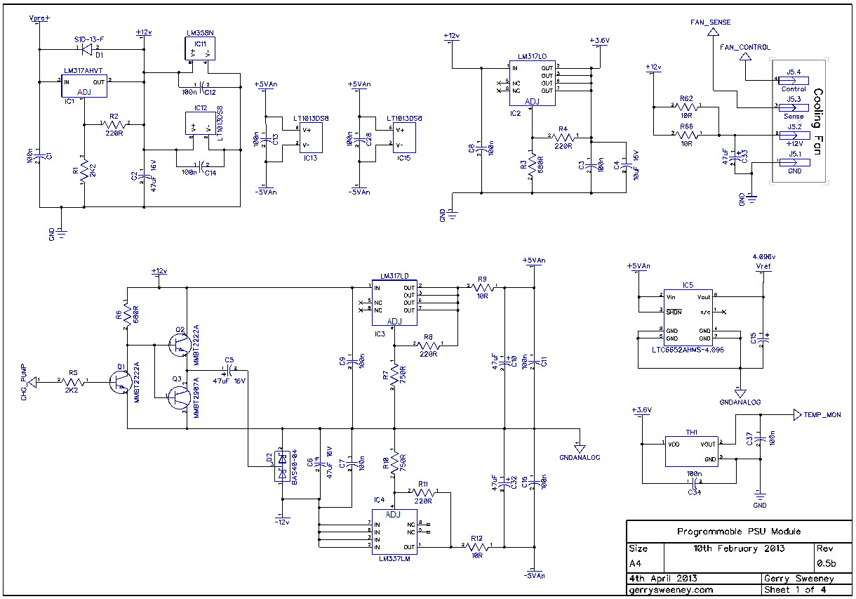
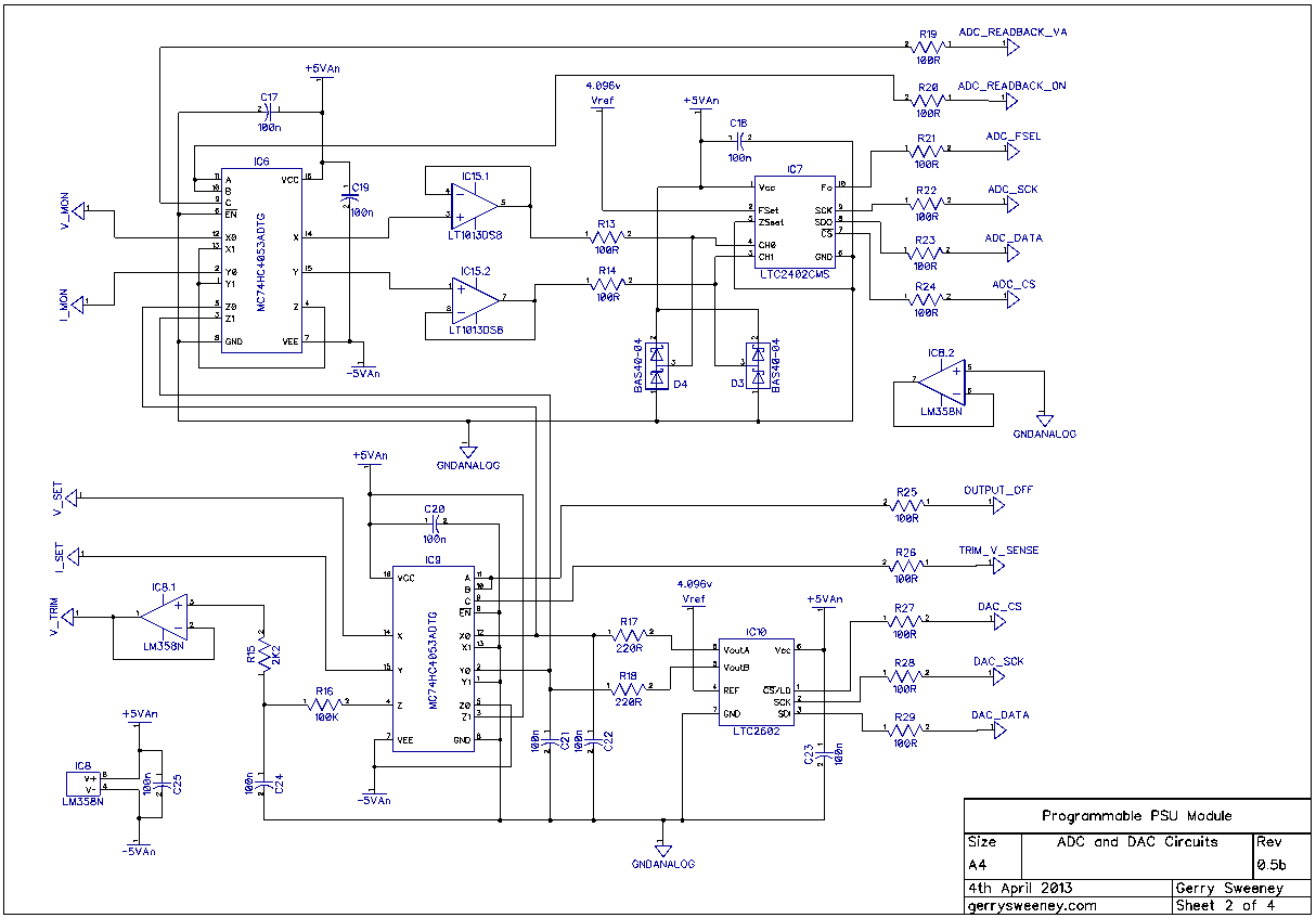
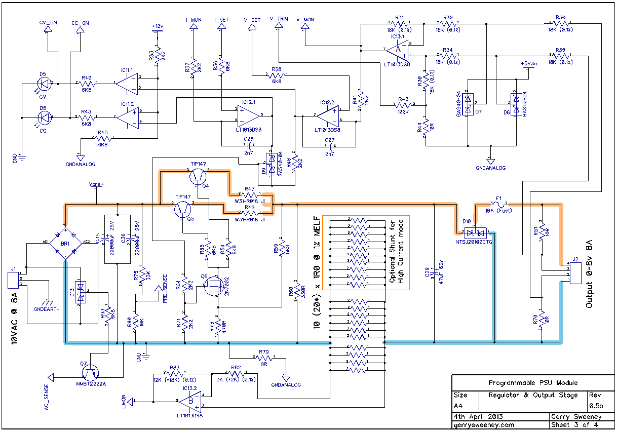
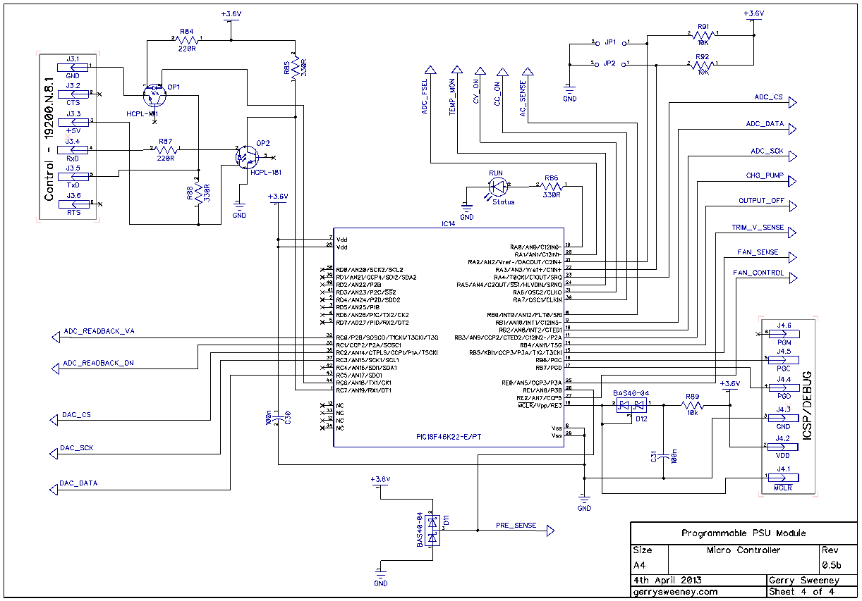
The PCB
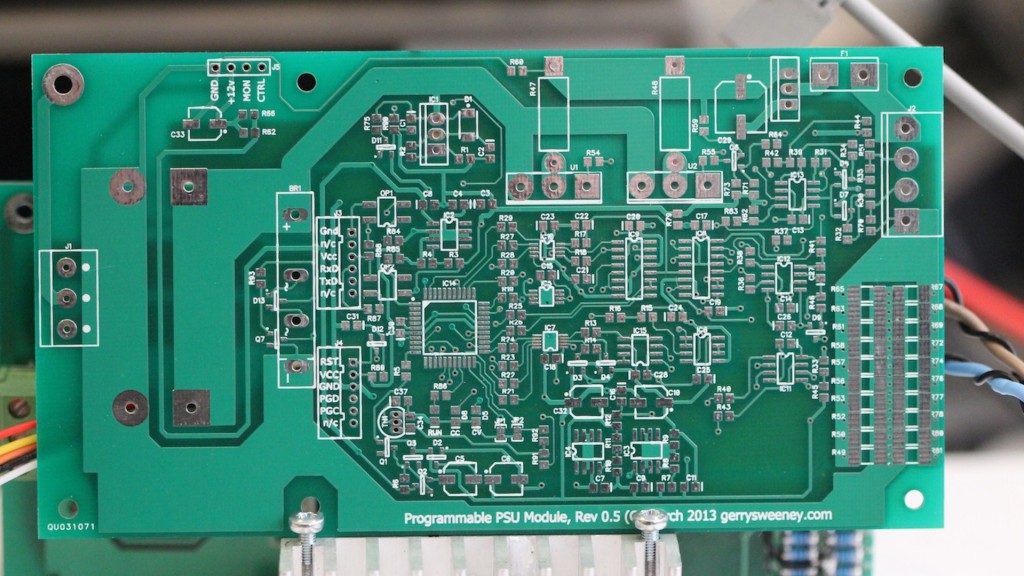
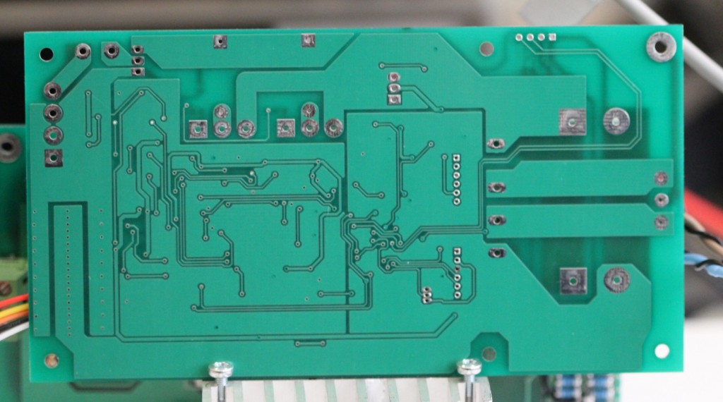
The PCB is made with 2oz Copper to handle current and provide better thermal mass. The high power path is run 5mm thick tracks (minimum) and run on both sides of the board. Where possible the top and bottom tracks are joined at the through-hole pads for the power components which is everywhere except at the current shunt resistor. For this I have many small via’s connecting the top and bottom traces to handle current and thermal bonding.
The BODGE WIRES
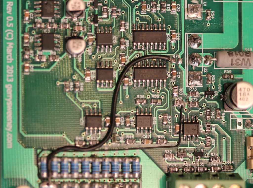
In laying out the PCB I forgot to pay attention to the star earthing I had set out in the previous post. The impedance of the ground path makes a big difference when you are looking at the lower 1mV of the range. Using DipTrace I had to use a ZERO ohm resistor to properly segregate GND and GNDANALOG nets, but I physically routed to the GND side of that resistor to the wrong point. I done a pretty similar thing on the low-side current sense connection. As a result there are two bodge wires on the board (see photo below). The first is the GNDANALOG to GND connection – Instead of installing R79 (which is ZERO ohm) I have taken a wire from the bottom pad down to the low-side of the current sense resistor array. The second is slightly more difficult to do, I had to cut the track from the top pad of R82 and then again take a wire down to the low-side of the current shunt resistor.
Thermal Management
In order to manage the thermal properties of the module, the firmware simply uses the temperature measurement of the heat sink to set the fan speed calculated on the following basis: –
- below 25 degrees centigrade – FAN is idle at its lowest speed (0% PWM)
- 25 to 50 degrees centigrade – FAN is driven with variable PWM 25 degrees = 1%, 50 degrees = 100%, which is a rate of 4% per degree of temperature rise
- more than 50 degrees centigrade – FAN is driven at 100%
Controlling a 4-wire fan is pretty easy, the specification developed by Intel describes the electrical interface and requirements for both fan control as well as fan manufacturers. I have added the Intel 4-Wire PWM Controlled Fan Spec as a download on this page for convenience. The fan I tested and used in the video above runs at about 1500 RPM to 3400 RPM with a 0-100% duty cycle on the PWM control signal. The taco output is open collector and provides 2 pulses per revolution.
Next time I am going to *try to* characterize the PSU. I don’t have much experience doing this which is why I say I am going to *try* – none the less I should be able to pull together some basic specs and test conditions.
Following that, I am going to design and make a front panel controller for the PSU. Although I am making this specifically for this project I am thinking about making this more generic so it can be used in other systems and/or test equipment. The basic goal is to create a single PCB front panel with a 4×20 VFD display, some buttons and controls, a micro controller (PIC32 or maybe ARM) with RS232, USB, Ethernet (and possibly a GPIB interface module) with 3-4 independent TTL level internal serial interface channels (to connect to PSU modules for example). Don’t know, all just thoughts at the moment, we shall see…
Thanks for watching.
This content is published under the Attribution-Noncommercial-Share Alike 3.0 Unported license.

Hi Gerry,
Another succesful demo…thumbs up. Speaking of thumbs up, I don’t use any of the social media so I can’t seem to add to any of the site benchmarks. In any case… well done +++.
A few questions if you don’t mind:
– What microcontroller is used now for the extra PWM?
– What temperature sensor is being used for the fan feedback? I thought I heard the word “filament”.
– What is your “go to” meter for bench testing? I see the 34401A and 87V(?). I’m about to get a new one to delve into some precision work.
– What’s the SMD fuse holder part number? I’ve been looking for something like that for a robotics motor board. The glass fuses look small until they are attached to the PCB.
Thanks again,
Mike
Hi Mike,
Thanks for the feedback, please see my answers below: –
WHAT MICRO-CONTROLLER
The micro-controller is a PIC18F46K22, its in the Part 11 schematic.
WHAT TEMPERATURE SENSOR
The temp sensor is an MCP9700A (sorry I missed that on the part 11 schematic). P.S. I hate the way the device mounts (or not as the case is) on the heat sink.
WHAT METER
This is a complicated question, it really depends. I like very much the HP 34401A because of its precision, but its less versatile because its mains earth referenced so in this case the Fluke 289 often wins out. The Fluke 87V is the best general purpose meter by far for many reasons, but the Fluke 289 is more precise. If the Fluke 289 switch on/boot time was instant like the 87V I would only have 289’s. But considering all factors today, if I was only allowed to own one meter it would be an 87V, if I could only own two meters it would be an 87V and a 289, if I was only allowed to own three meters it would be two 87V’s and a 289, and if I could own four or more I would have two 87V’s, a 289 and a 34401A. Anything more is just nice to have (and probably overkill too)….
WHAT FUSE
Its made by a company called LITTLEFUSE. This is the Farnell order number is: 1817191 (http://uk.farnell.com/littelfuse/0154008-dr/fuse-smd-omni-block-f-8a/dp/1817191)
Gerry
Hi Gerry!
Thank you for the great videos!
I have a question about another meter(s) – Fluke 189(187) – do you have some experience with those? If so, how would you compare 189/187 to 87V?
I know they are not in production anymore, but still very popular(at least from what I’ve seen on the net).
Thank you in advance
Alex
Hi Alex, thanks for the feedback. On the question of the meter, I have not used a 189 or 187, I suspect they are probably similar to the 287/9. The main problem with the 287/9 is the switch on time, it takes about 9 seconds from switch on to be ready to use, the Fluke 87V is near instant. If you have not seen it, this page and search for WHAT METER I explain more there. Gerry
Thank you, Gerry, for the reply!
The switch on time of 287/9’s is the precise reason why I’m looking for another multimeter – some times it seems painfully slow for a one-time measurement.
Anyway, thank you once again and I’m looking forward for more videos/blog posts
Keep up the great work!
Alex
Alex, your welcome. Its also worth noting that although the 87V is a mere 20,000 counts meter :! while the 289 is 50,000 counts, the 87V does have a High Res mode which does give you four digits to the right of the decimal place for lower voltages. The 289 is in high res mode by default, on the 87V you have to switch it into the high res mode (by pressing and holding the backlight button for a couple of seconds). Gerry
Thank you for the information. BTW, the PIC18F46K22 has a couple of minor but possibly applicable errata for the EUSART.
Mike
Hi Mike, I have not noticed any issue with the EUSART, the serial comms is working fine, but I will keep an eye out.
Hi Gerry,
are you willing to share the updated schematics for your design?
BR, Jonas
Hi Jonus, yes of course, I will get the part 12 article updated tonight. Really not much changed but you are right I should have put the latest diagrams up. Gerry
Hi Gerry,
I’m really enjoying this series of videos following your design process. Looking forward to the next one!
Thanks
Paul
Thank you Paul, glad you are finding it interesting. If you have not already, you can subscribe to the blog at the top of the right hand panel to receive notifications as I post new content. Gerry
Hi Gerry,
Thank you for uploading the schematics. JP1 and JP2!? Some secret configuration settings?
And why are you using high-power ballasting resistors? Wouldn’t a 0.5-1W be enough?
BR, Jonas
Hi Jonas, currently there are various settings in the control software to determine things like the volts and current gain and precision, this is set depending on the voltage/current mode for the module. Because each mode requires different resistors in parts of the circuit I thought I would move away from having to config through software and config through jumpers. This gives four mode possibilities which matches the four modes I highlighted in an earlier post. They are not yet implemented but they were easy to add, they are solder blob type jumpers so just two additional resistors that were already in the BOM. As for the ballast resistors I was using 0R018 because thats what I had lying around so I know that value works. 0R1 are much more common and at 4A each device that would be 1.6W per resistor, double that for headroom and 3W resistors is where you end up. As I had the space, and I wanted the through hole component to connect the top/bottom tracks and the resistors act like jumpers giving me more track routing options and these 3W resistors are the most common format and therefor low cost too. Gerry
Gerry, a good series. You’ve not spoken much of the preregulator, recently? Years ago, i tried a preregulator – a thyristor after the bridge rectifier before the main capacitor. A simple control circuit either deleivered a mains half cycle to the supply capacitor, or skipped it. While it worked, it sent massive short current spikes through the transformer (causing it to saturate and overheat), and probably didn’t do the mains caps any favours, with massive ripple current, either! So I abandoned it. Is your idea more “phase controlled”?
Hi Laurence, there are two approaches, the first would be phase controlled, it would be horrendous trying to switch into a live cycle at a slow rate. It would run at 100Hz on the full-wave rectified signal and act like a charge pump. The second option would be to run the switch with a high speed PWM, this would limit the current per switching cycle because of the narrow time window – think Class D audio with the smoothing cap being the low pass filter. I have not progressed the pre-regulator for Version 1 because its a whole subject in its own right, I actually would really like to design a high(isn) powered buck/boost regulator for a pre-regulator but that will be another project I think….
Hi
you used MAX4080 which i also intend to use in my project. what SOIC to DIP adapter did you use, may you give me the full specs i’m stuck
Hi, I changed the design and moved away form the MAX4080 in the end, its still a good chip but I could not get the offset accuracy I wanted. Unfortunately the SIOC adaptor I used I had for a long time and cannot find the supply of them anymore. I have used a number of other adapters which you can get on e-bay for just a couple of $, search ebay for SOIC adapter and you should find many of them.
Project looks like it’s coming along really nicely, just finished reading/digesting all 12 parts (incl. the prequel hp/agilent repair post) and known now to keep an eye out on this blog! 🙂 Can’t wait to read the next part and almost wish the series would not end as i’m learning tons.
Quick question, what board house do you use to get your protypes made? I’ve looked at a few, but most have a min requirement of 5-10 (lowest i seen was 3 via OSH Park), but really when you are just testing/iterating through your layout, getting more than one is a pain.
So my question is, how do you approach this part, do you order several boards to meet a minimum (or for other reasons), how long is the typical turnaround time from when you order to when it arrives?
I might just try/practice fabbing them myself at home for one-offs (or single-sided ones, yours is two layers/sides i take it?) and when the layout not being that complicated, but would prefer a more professional approach and you seem to more than know what you’re doing 🙂
Hi Alex. Thank you for reading the blog. You can subscribe to the blog for notifications to make it a bit easier to follow. I have tried a couple of board houses, they are all much the same and I generally get 4-8 boards made at a time. Mostly because when you order it only adds a few cents from say 2-8 boards before the price starts to climb so you may as well order as many as you can for about the same $. In practice though, even for a prototype you probably want four boards so you can build a couple up and hack around a little. I am in the UK, I have used QuickTeck and Silver Circuits, I have also recently used ITeadStudio OpenPCB which seems very good for the price. For the cost of chemicals, equipment and the time spent messing around along with the mess and general aggravation I really don’t think its cost effective doing DIY FAB at home now days, its just to convenient and cheap to get boards made by an expert factory geared up to do it.
Greetings.
I’m starting to redraw your schematic for my own needs (too loud words for me, heh).
I’ve got some questions about supply circuits:
1) Is voltage divider of IC2 correct (which provide 3.6V)? Looks like there is 5V.
2) Can i use 3.3V instead of 3.6V, if it possible?
3) Why do you use resistors R9, R12?
And one question else: can we’ve get software and firmware in close future for PSU module?
I’m not sure that i can make a good PCB, but i’ll do my best.
Thanks.
Sorry for silly question.
1. The divider values are correct, I am running the micro on 5v, the schematic is wrong (I forgot to change the label). I moved to 3.6v for a while because of a micro change I made but I recently switched to the current one which I run on 5v. This is better because the ADC/DAC chips have to run at 5v so the logic signals are at the right levels.
2. I would suggest running the micro at 5V, not 3.3v
3. Resistors R9/12 form a low pass filter with the 47uF caps to help reduce regulator noise for the analog circuitry. Not sure how much it helps but it certainly does not harm having them there.
You should be aware, I still have design changes to make, I will be posting Part 13 soon showing some op amp changes. You may want to hold off putting time in re-drawing just for now. I will also be getting some PCB’s made and making them available if people want them once the final design is complete.
I will be making the firmware available, I need to remove some closed source code from it that I used to for speed of development, I will have re-implemented my own code by the time its finished.
Gerry
Hi Gerry,
Nice work here ! Could you be so kind to give us some additional info about PIC firmware? I like your control software too, can you tell more about software environment used for creating that ?
Cheers,
Nicu,
Hi Nicu, Thank you for looking at the project. I plan to post a whole article dedicated to and overview of the software side of the project. The firmware is written in C using Microchip’s XC8 compiler and MPLAB-X development IDE. The control software is a very quick lash-up in C++ using Qt, I am developing on OSX/Mac but the software builds and runs on Linux and Windows. Because of the work on the hardware, the software/firmware is still very much in its infancy and subject to lots of change. Once I have settled on the hardware design I will focus on the software and get it documented and posted in the series. Gerry
I’d be interested to hear why you elected to make it an LDO regulator (PNP series pass) instead of a standard (NPN series pass) regulator. From the look of it, you’re not going to be ‘battery powered’, so you can elect to use a mains transformer with a secondary voltage that can deal with the larger (2*Vbe+Vsat) drop out voltage in a standard regulator.
I’ve been told it’s far easier to make a standard regulator ‘unconditionally stable’ than an LDO regulator. A single MJ15003 NPN driven by a $0.05 2N2222A as a darlington pair ‘should’ handle more current than your pair of TIP147 devices? (I might be way off on that aspect though… Still learning)
Hi Trev. I did not specifically follow the LDO regulator design pattern, I chose the output configuration for a number of reasons. Mostly it was simplicity and reduced component count. The TIP147 is the right physical package and they cost less than £1 each. I moved away from a MOSFET because I did not have the headroom to drive it, but I really wanted a voltage amp rather than a current amp which is what the MOSFET gave me. The TIP147’s deal with amplifying the current, I chose a darlington device so all of the power dissipation would be in the single device rather than the device and its driver. You mention the MJ15003 which has a hFE of about 25, so it would need at least 320mA of base drive to get 8A through the power device, so even at only 12v drop across the regulator that would be 3W of power in the driver – way too much for a 2N2222A. The TIP147 has a hFE of 500 or more so I can drive that with what is effectively a voltage amplifier (the MESFET driver). I wanted controlled voltage gain with local negative feedback which is a voltage feedback look so it all worked out well with a very low component count in the end. The stability is obtained by putting the negative feedback in the driver, significantly reducing the error op amp’s influence in the gain loop. There is probably a better way to describe it than I have just managed but from my tests so far its working really well. I have not seen any other regulator design like this, although I can’t imagine it has not been done before. Gerry
Hi Gerry,
I have been following your posts on the power supply very closely for a long time now. I stopped halfway in the process of designing my own programmable power supply when I came across this thread – and have been eagerly awaiting your project to finish before I reconsider my own approach. I have already learned an incredible amount from your blog and between you and Dave (on EEV Blog) found anew passion in EE. Please continue the good work. thanks for all the goodies – cheers.
Hi, thank you for the feedback and encouragement, it is nice to know that my efforts are useful to others. Gerry
I just wanted to say thanks for posting all these write-ups, plans, and videos. While your final design might be ideal for you, inevitably there’s a slew of trade-offs in EE. Witnessing this evolution (eg. hi/lo side metering, BOM simplification) was FAR more instructive than a single “perfect” snapshot. Thanks.
You are most welcome, thank you for the feedback
Gerry