In Part 5 I talked about the target ranges that the PSU module should be able to support and expanded in detail on the voltage range calculations, and I said the next part would be looking at the DAC control circuitry. However, I really need to do the same exercise for current limit control in order to understand the required current control voltage range and resolution we need to ensure our DAC selection is appropriate for our current limit control too.
Current sensing starts with a “current shunt” which is simply a low value resistor in series with the load inside the power supply that will drop a small amount of voltage across it that is directly proportional to the current flowing through it. Selecting the right value is critical to ensure that your current sensing circuit operates in the correct range while making sure that the power dropped across the shunt resistor does not take the component outside of a reasonable thermal range, ideally you want your shunt resistor to run at ambient room temperature under the largest supported load. The PSU design calls for current handling of up to 5A. Just like in the DAC calculations we want to aim for nice round numbers so we pick a resistor value that is going to meet all of these requirements. In the design I have chosen a value of 0.1 ohms which if you do a simple OHMS LAW calculation “E = I / R” you will see that for a 0.1R resistor we get 500mV dropped across it when 5A of current is flowing. The amount of power dissipated in the shunt resistor at 5A can be determined by the formula “P = E x I” which works out to be 2.5W so we need to make sure that our chosen resistor is able to deal with that power and adequately dissipate the two and a half watts of heat generated.
A 0.1R resistor is a common high-power resistor value, and for 5/10W resistors they are typically a wire wound construction. However, the tolerance on these resistors is around the 5-10% mark which we need to take into consideration. Just like the potential divider in the voltage sense circuitry, the current sense resistor is the only component in the circuitry that has a direct bearing on the accuracy of the the current sensing, so a 5% tolerance is really not good enough for what we want. Unfortunately, as soon as you need precision at low resistor values things start to get very expensive. Think about this, if you want a 0.1R resistor at 1% precision then our tolerance needs to be +/- 0.01 ohms which is very hard to make, hence the cost. I do wan’t the precision but without the cost, and am happy to be within 1% for the current sense, so a nice solution is to use 10 x 1R 1% 250mW resistors in parallel to create a 2.5w 0.1R 1% resistor. These resistors are cheap at just a couple of cents each and the tolerance will be tight enough that any error can be easily trimmed out in software calibration. The prototype I built uses through-hole parts that are soldered in but mounted about 5mm above the surface of the board providing airflow around them to help keep them cool. In production I may opt for using SMT resistors and a larger copper area to help dissipate the heat. Here is a photo of the construction described.
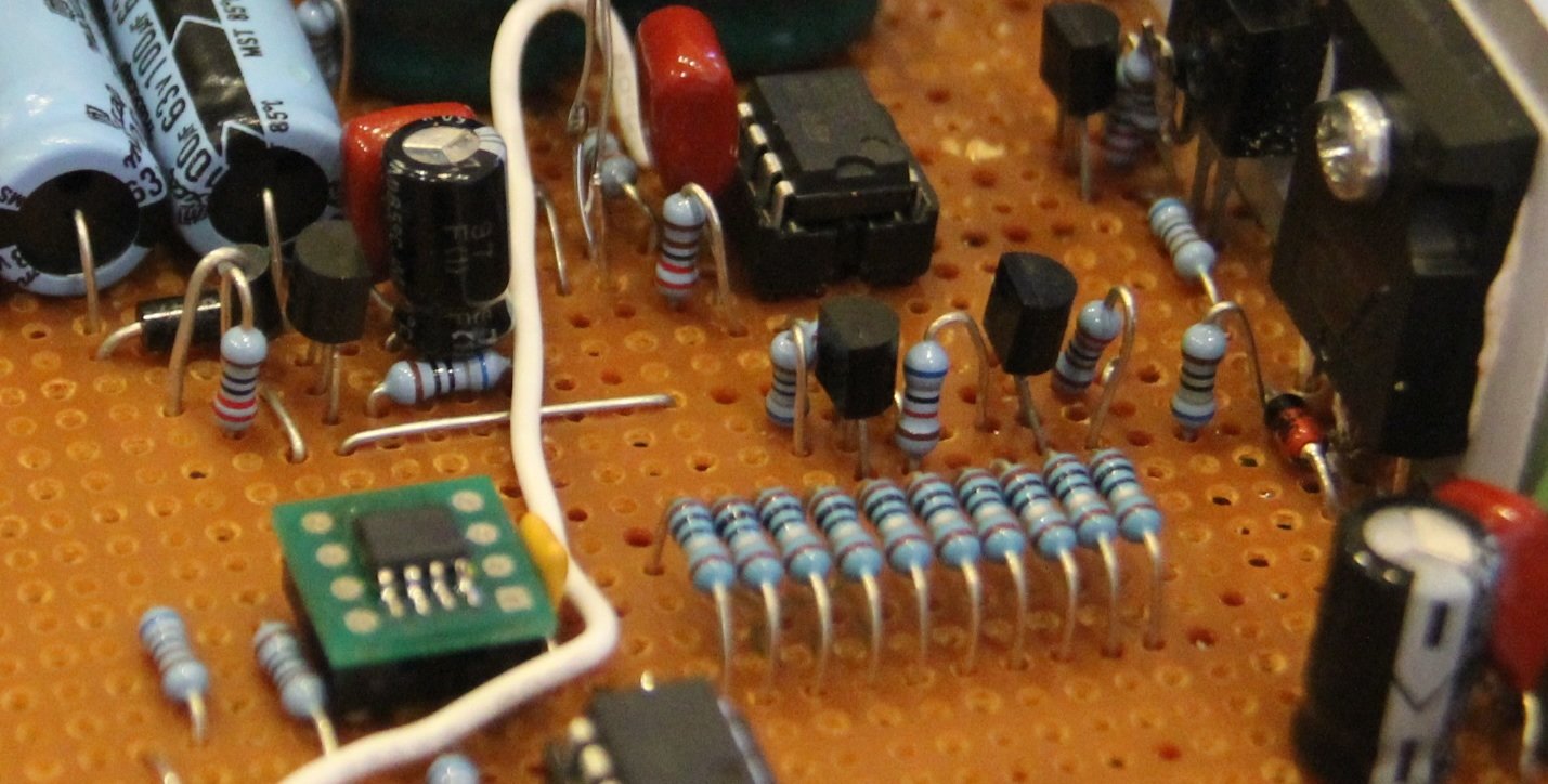
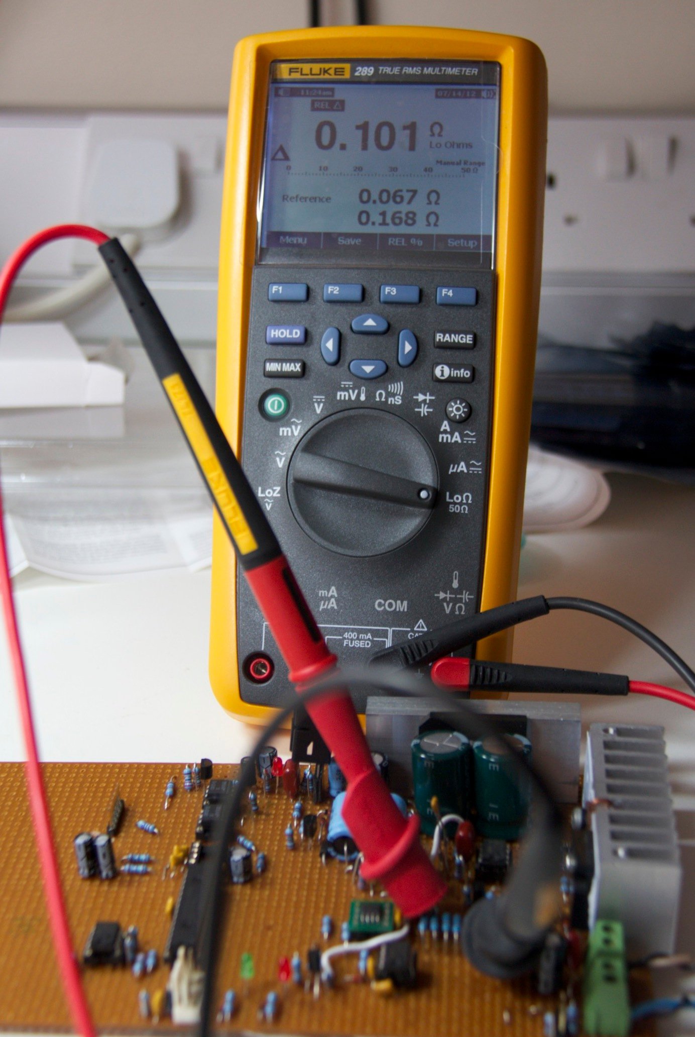
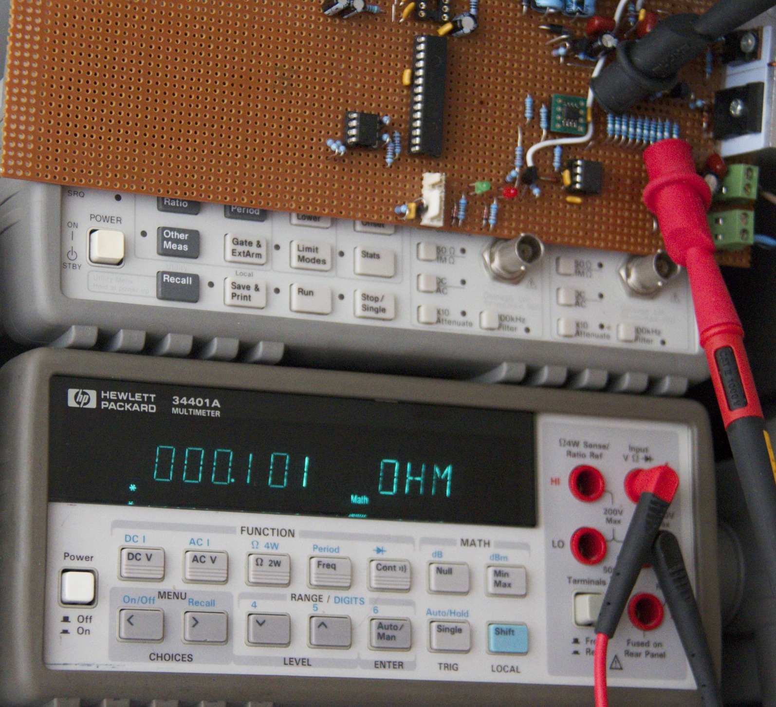
If accuracy beyond 1% is important you can hand pick resistors from different manufacturers batches and try to match the resultant restore created. If you fall slightly above the desired resistance you can trim it down by adding higher values in parallel. Or you can go down the “buy an expensive precision shunt resistor route”. In testing my own shunt though, I found I was within a few miliohms of 0.1R which is about what I would expect for 1% tolerance resistors. When measuring these resistances you need a meter that has a Relative or Null mode because you need to compensate for the meter leads and the mechanical contact. I used decent fluke leads and the supplied heavy duty croc clips, I used two different meters and nulled on the croc clips being shorted together before measuring the resistor. Here are the results…
Measured with a Fluke 289 on the low ohms range
Measured with a HP34401A on the ohms range
Now we know that our current sense resistor is good this will give us 0 to 500mV for 0-5A of current we need to sense that voltage and scale it up so we can do something useful with it. The MAX4080F I talked about in Part 4 does both of these things for us. This device is a purpose made high-side current sense amplifier and precision x5 gain amplifier with a buffered output. Being a high-side device its powered from the +V rail so we don’t need to do anything special. In our configuraiton and the x5 gain of the MAX4080F part we now have a buffered output voltage in the range of 0-2.5v for the current range of 0-5A. This control voltage is fed to the constant current error amp on the negative input creating a control loop that prevents the regulator from delivering any more current than is programmed. The current is set by applying the same voltage on the + input of the current error amp as the voltage that will be seen on the output of the MAX4080F device. If we provide a reference voltage of 500mV then the regulator will limit output current to 1A – Nice…
I thought it worth covering the two main schemes you can use to measure DC current in a power supply when using a current shunt resistor – these are known as high-side and low-side sensing.
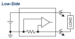
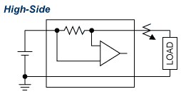
NOTE: The above illustrations are from maxim-ic.com and are Copyright © 2012 Maxim Integrated Products
High side sensing is done on the hot regulated rail, often before the regulator pass device, whereas low-side sensing is done on the ground return path from the load. I have used high-side current sensing in this design because its the significantly better of the two schemes for a number of reasons, and its simple to implement because the MAX4080F makes it so. In the absence of such a useful single low cost purpose made device, then it could be tempting to go with low-side sensing because of simplicity. However, low-side current sensing designs introduce problems that our design will probably not tolerate. In low-side sensing the current sense resistor is placed in the load’s return path to ground, this has the undesirable effect of disturbing the common ground of the overall system when under load which can lead to stability problems, especially if we are doing remote sensing. Even worse than that is the risk that in a lab setup you are using a ground referenced PSU and in your test setup you ground your negative terminal of the PSU that has low-side current sensing which will effectively bypass or at the very least degrate the current sensing capability of your PSU which could cause a lot of damage, especially if your short circuit protection depends on the current sensing. Another problem with low-side sensing is as the current increases the ground reference and sense point will move apart as more voltage is dropped across the current sense resistor, this will introduce offset errors in voltage sensing. Low-side sensing is easy to do and easy to measure with a cheap op-amp but high-side current sensing brings so many advantages that $2 for the MAX4080F or another device like is money well spent I think.
One minor problem with the MAX4080F for this design is the common mode range of the device, the data sheet says it only goes down to 4.5V which is likely to be a problem in the case of a short circuit on the PSU output, really the common mode range needs to be able to extend to zero. I will need to test further to determine if it will be a problem in this design and possibly identify an alternative device – if anyone knows of any that are worth looking at please add a comment.
So back to the PSU, a quick recap on the ranges we are woking towards but this time with a focus on current sense and control.
| Range | Current Range |
Current Set Resolution |
Full Scale Sense voltage |
Volts per Milliamp |
Current Steps |
|---|---|---|---|---|---|
| A | 0-5A | 1mA | 2.5V | 500µV | 5000 |
| B & C | 0-2A | 1mA | 1V | 500µV | 2000 |
| D | 0-1A | 1mA | 500mV | 500µV | 1000 |
As you can see from the table above we have a more limited control range requirement so one configuration covers all ranges. However, there is a slight problem inasmuch as the design only gives us 2.5v out of the high-side amp at full scale, which is only 500µV per step which is half of what we get from our DAC at 1mV per step with a 4.096v reference. I can divide down the DAC output by x2 but then I fall short of the target range of 5A so I am going to have to rely on increasing the DAC’s resolution by modulating the DAC output – only measuring this physically will verify if thats good enough. Now we have a good sense of the control ranges need, in Part 7 I will work up a circuit, get a micro controller talking to the DAC chip and do some some perormance measurements to see what we come up with…. I know I said that in Part 5, but this time I mean it 🙂