I recently bought a faulty Agilent E3631A bench power supply on e-bay which I thought would be a nice addition to my *slightly excessive* electronics hobby workbench. These power supplies are really nice; they are engineered and built like military equipment, good high quality materials and mechanically very robust. An great indication of how good these things are is the second hand values, these things cost $900-$1000 to buy in reasonable condition so they are not cheap. I bought this particular one faulty and thought I would have a go at repairing it.
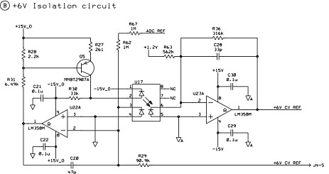
My first impression of the electronics in side was not great, it seemed very seriously over engineered for what it was trying to achieve. It seemed like the designers had a field day adding all sorts of crazy circuits because they could. The ADC is made up of discrete IC’s, there is a custom logic chip in there as well as a CPU, ROM and RAM, there are numerous power supplies for bias and control circuits all floating around each other and most things seemed much more complicated than they need to be. The one real surprise though was the opto isolation in the analogue domain. The CV and CC reference signals from the DAC for the +6v supply are isolated through high linearity opto couplers type HCNR200, this is something that would be crazy to do today when the cost of micro-controllers are so low and have all the goodies like DAC’ ADC’s and PWM’s making isolation in the digital domain a far more sensible design choice.
In fairness though, I was making my initial judgements based on what’s possible with today’s components, things were very different 20 years ago so given its age it’s a pretty sophisticated piece of kit really. Once working it does appear to work very well so my initial thoughts are not really founded on anything other than my own instinct to want things to be easier to understand and better as a result.
On with the repair….
First things first, after a quick check of the obvious big components like the series regulator transistors etc, I very quickly needed a schematic diagram. Agilent were less that helpful here, the manuals they put out now days specifically have the detailed schematics removed from the documents despite there being a reference to them in the index. When I contacted Agilent and asked for a schematic I was told in no uncertain terms (after a 4 day response time) that they no longer make the schematics available, but they do offer a £450 exchange repair service – come on HP/Agilent, by all means offer the service but don’t stop those of us who want to hack around from doing so. The solution was to buy an original printed service manual which did include the schematics; e-bay and $10 got me what I needed. As luck would have it, while waiting for the manuals to arrive in the post, I also managed to find a manual on the net which still had the schematics present – not from any official Agilent source I might add…
I set out to work on fixing it and found I had to strip it down completely, removing the two boards, front panel, transformer and wiring from the chassis and spread it out on the bench. If you find yourself needing to repair one of these, be prepared to commit serious bench space to the exercise. I have taken a bunch of photo’s if the teardown so you can see what all the bits look like.


There were various faults with the PSU, numerous op amps and some CMOS logic IC’s were faulty as well as two open circuit 33k resistors. At a guess I would say there was some kind of big static or high voltage discharge into or across the outputs that caused the original fault. I had to isolate the various areas of the circuit and work on them individually, making assumptions about what should be present in terms of voltage levels and feed in lots of external signals to get to the bottom of each fault. I struggled with the configuration of some of the analogue circuitry – fortunately for me I have a good friend who understands much more about analogue electronics than I do so some exchange of e-mails and sections of circuits with measurements kept me on track and expanded my own knowledge too – cheers Span.
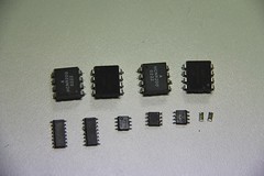
Here are all the components I ultimately had to change…
While fixing it I also managed to introduce some faults of my own. Specifically I managed to blow two of the HCNR200 opto couplers, easily done just with a slip of a multi meter probe shoring out pins 2 & 3 puts 15v with no current limit straight into the internal LED rendering it open circuit instantly. I managed to blow four of them like this before I figured out what I kept doing – doh!
After working through these problems I finally got it working except — when placing a dummy load on the +6 output, the voltage I was measuring went up! A bit more inspiration from my friend Span and a scope on the output and voila – it was bursting into oscillation under load, probably due to the 4 ohm wire wound load resistor. It turned out this was down to the fact that the electrolytic capacitors soldered onto the back of the binding posts on the front panel are actually there for stability reasons – obvious once you know. I had removed the output wiring from the front panel to make it easy to work on. Strapping 1000uF across the output solved the problem.
You can download the Agilent E3631 Service Guide which include the schematics
Having worked on this I have been inspired to have a go at designing my own programmable PSU from the ground up to see if I can match the specs but use more modern components and design approach – I will post info on progress if I get around to it.
[UPDATED:] I am getting around to it… http://gerrysweeney.com/fully-programmable-modular-bench-power-supply/
This content is published under the Attribution-Noncommercial-Share Alike 3.0 Unported license.
Attachments
| File | Description | File size | Downloads |
|---|---|---|---|
 Agilent E3631 Service Guide
|
6 MB | 8821 |
I found another teardown of this PSU here http://www.eevblog.com/forum/product-reviews-photos-and-discussion/teardown-agilent-e3631a-power-supply-(picture-heavy)/msg68520/#msg68520
Wonderful work. Thanks for making it available.
Great blog,
hope you get enough time to update it more often.
Thanks for your comment. I do enjoy producing the blog content but my time is limited, I will do my best.
Really appreciate the schemos, as some grad students took issue with a lab supply we have and rendered it inop. Not sure I really want to work on it, but I do get paid for this.
Glad you found it useful. Good luck with the repair, they are fun to work on. Gerry
Hello,
GREAT post. I have been reading alot of the posts about the E3631A and have learned a bunch. I have a Three E3631A power supplies that have failed. They are doing almost the exact same thing with some Small differences. When I turn the Output ON and try to adjust the Voltage on 6V or 25V or -25V the display will NOT change However the voltage OUTPUT does go up and down (on the other it does the same BUT the display has eroneous numbers displayed, AND the Third one will change just a FEW volts on the display). When I enter into the Limiting section the Voltage as well as the Current is adjustable just fine. I have after studying all I can, Verified all supply/bias voltages per the Manual/Schematic (and believe me with 3 different Ground points that wasnt very easy…). I also know it is Not the front display PCB or the Bottom PCB as I had another working unit to do some swapping around with and verified I do have a Top PCB problem???? Any help would be so very much appreciated.
Hi Jack, have a look at this repair, this was closer to the problem you have. http://gerrysweeney.com/hpagilent-e3646a-power-supply-teardown-repair/ might be of help. Gerry
Jack, how did you get on with this? I’ve just picked up an E3631A with the same problem; all 3 outputs work fine but the voltage and current read back is wrong when the output is switched on. Looks like it’s end-stopped if you know what I mean, +6V always reads -21.23V,7.629A, +25V reads -34.41V, 1.942A and -25V reads -34.42V, 1.944A. I suspect something around the DAC, hopefully simple. I’ve not yet had a chance to open it up and check the power supply voltages.
Did you see TheSignalPathBlog’s repair video on youtube? He repaired an E3634A with a similar fault.
Pete
You might want to see these other two articles. All of the HP PSU’s have roughly the same circuitry and I have seen the fault you describe, its definitely in and around the ADC, should be easy enough to fix, its most likely to be a failed reference supply.
http://gerrysweeney.com/hpagilent-e3646a-power-supply-teardown-repair/
http://gerrysweeney.com/hpagilent-e3634a-power-supply-teardown-repair/
http://gerrysweeney.com/my-e3634a-mystery-explosion-wtf/
Gerry
Thanks Gerry I should have mentioned that I’d already viewed your other videos and found them very helpful.
I got a chance last night to open the PSU and check a few things. First thing I checked was the ADC REF voltage from U2 (LT1021DCS8-5). It’s a 5V precision reference but although it was getting 12.3V on the input the output was 200mV. Aha, I thought, that was easy. Too easy it turns out. I got an AD584 reference I had lying around used the same 12.3V feed to drive the 5V ADC REF signal. That worked and the 5V held up however the original problem still remains. The ADC REF is used in a lot of places but I guess the next logical place to look is the input op-amps U3A and U3B and trace the signals through the ADC circuit.
Pete
Hi Peter,
Yeah sounds like a typical fault finding expedition on these things. Check all the reference voltages on both sides of the opto isolation and make sure you identify your ground points if you want to maintain your sanity. Good luck with the repair.
Gerry
Only wanna tell that this is very useful , Thanks for taking your time to write this. ddefgdaaefae
Thanks for the feedback, glad you found it of use.
Gerry
Hi Gerry,
Thanks for taking the time to write this, it made interesting reading. I was hoping you might be able to offer some advice on repairing my own E3631A. It works fine, if you connect a multimeter to the output you get 0-6v, 0-25v, etc but! the display only displays -2v and 1A on 6v range (or +20v and 0.007A on 25v range) I also checked via GPIB and it says the same as the display. This display does not change if you use the wheel to turn the voltage up or down (although it does change the actual output) Sounds like a readback fault of some sort but not sure where to look. Appreciate any hints
Hi Ben,
You need to check the reference voltages all around the ADC circuitry, its probably one of them. If not that it will be a fault with the ADC circuit its self which is tricky when you repair them for the first time. Use the schematic, establish your ground references and then check all of the voltages for correctness.
Gerry
Thanks Gerry, only 2v on the +6v CV Ref line so I guess this is the problem.
Track that down and you should have a working PSU, good luck with the repair Ben.
Gerry
Hi Gerry,
Very useful repair info indeed. I am myself trying a cleanup on a similar device.
I would like to know how you managed to remove the front panel. I would like to clean the contacts beneath the buttons… but I am afraid to break those plastic tabs.
Keep up the good work,
Dikran
Yes the front panel came apart no problem, the PCB basically slides out, you do not have to move the plastic retaining tabs that much so I think its pretty safe.
Gerry
HI Gerry,
I’ve bought a Agilent E3631A Power Supply Unit (PSU). Whenever I switch it ON, the house Earth Leakage CB (RCCB) is tripping. When I measured the voltage between Unit Chassis and Supply Earth, it is around 175 V AC. I opened the PSU to look for any active wire touching chassis, but could not find any. Could you please suggest what could be the reasons behind this?
Cheers,
Raj
Raj,
I would first have a look at the common mode input filter on the mains side, there is probably two caps from the line down to earth, one might be short circuit. Other than that you may have a short in the mains transformer which will be a much bigger problem. Its hard to say without looking at it but it sounds pretty easy to work out whats wrong.
Gerry
Hi Gerry,
Thank you very much. I’ll have a look into it.
Cheers,
Raj
Hi Gerry,
As you said, I had a look into the input filter area on the mains side. There were two caps and next to these was a ground wire screwed to the PCB. I’ve moved the ground wire a little away from the caps, and the issue has fixed.
Thanks a lot for your help, and apologies for the late reply.
Cheers,
Raj.
HI Raj,
Glad you got it working.
Gerry
We have 3 of these where all 3 have a problem with the control on the front barely works/operates. Any ideas?
HI Roger,
Not sure what you mean by barely works?
Gerry
Very efficiently written information. It will be beneficial to everyone who employess it, including myself. Keep up the good work for sure i will check out more posts. kedbebcedfce
Gerry, a great post and info! Thanks for all the hard work you put into this. With this info, I now have the information needed to repair our bad supply.
Hi Robert,
You are welcome, I am glad it was helpful for you. Good luck with the repair.
Gerry
Hi Gerry,
This has been a very useful resource for me. I’m wondering if I could get your advice on a problem I’m experiencing…
I have the same exact supply (HP 3631A). When I push the power button, the display turns on for about a second, and then turns off and a single ‘beep’ is heard. In The Signal Path’s repair video (found here: https://www.youtube.com/watch?v=vbjSWxWXurE) he troubleshoots the same exact problem, but I don’t believe I’m experiencing the same fault.
I’ve managed to get access to a thermal camera and I have observed that F1, U21, and U26 on the top PCB are reaching temperatures of ~100C. Also, U21 on the bottom board is reaching about the same temperatures at start-up. I have yet to begin probing places on the board, as I’m not entirely sure what I should be looking for. I have checked the levels of the bias supplies for the +/-25V power circuit, front panel, and floating logic and all seems okay there.
If you have any advice to offer up I would really appreciate it. Hopefully I can bring this unit back to life! Thanks in advance for your help.
Hi Mitchell,
Its hard to be specific without getting a DMM out and probing around, if you have that much heat dissipating you need to locate the source of the load and isolate it. A good starting point is to check *all* supply and reference voltages. Good luck with the repair.
Gerry
Gerry:
I have a E3631A. Two problems. I was charging a battery with it. I accidentally plugged the battery to the +25V output, with reverse polarity. It smoked a couple traces, which were easy to find. I also melted the +25V supply current sense resistor R66. Soldered back in. Powered it back on, both the current and voltage adjustments work for both +/-25V supplies, but the current is always showing 2.xxxA regardless. The current limit works correctly between 0~ 1A.
Checked R63, CR36, CR24 and CR25 are ok.
DOn’t know what to check next.
THe other problem was already present when I got this supply as scrape, the +6V supply works, but the current limit adjustment does not work.
I am afraid you will need to work through it step by step with the schematic, it could be anything really
Gerry
I have several E3631A power supplies that are having readback issues. You can accurately set the supply for the voltage you want while in the limits mode, but as soon as you push the limits off and it goes into actually telling you what the output voltage is, the display is all zeros. The output is what you set it too, but display reads zero. This is only for the +25 V output, the 6 volt and the -25 volts all works great, you can set the limit and then view the output on the meter. I have gotten pretty good at cleaning the encoder controls and calibrating the output is also easy, however because of the readback issues, the supply will error out and fail the cal, it will perform the 6 volt and -25 volt calibration but will error out with the +25 Volt attempt. I have also went the route of contacting Agilent (Keysight) and asked for assistance but all I got was them telling me to ship the supplies in for a 500 dollar refurbished swap. No more parts and as you indicated, no more schematics (quickly downloaded your copy…thanks) Anyone come across this problem.
Howdy folks. Before I ask the question, I thought I would share a quick fix for a common problem with the E3631A power supply and 33220A function generator. The control knob or what I have learned is actually called a rotory encoder (newer version of an RPG?) has a bad habit of acting up and not being able to control the settings. Simply clean the encoders by taking them apart, cleaning the contacts, lifting the spring contacts up a bit, and putting the machine back together. I have probably cleaned and restored function to at least 30 machines. With the power supply, you don’t even need to remove the covers. You can remove the front panel and display board with just 4 screws and the knob nut, you then remove the 4 tabs holding the top part of the encoder, clean it and put it all back together, I have yet to have a unit not benefit from that effort.
But has anyone figured out what is causing the readback issues with the power supplies. They are failing and the symptoms are basically the same every time. The unit will produce full voltage and current outputs but only in the program mode. Once the program mode times out or you manually exit the mode, the output voltage is still there but the display either reads zero or some random number unrelated to the actual output.
Thanks for any input you guys can provide. Peace and thanks for the manual with schematics download.
I’m not sure where you are getting your info, but great topic.
I needs to spend some time learning more or understanding
more. Thanks for excellent info I was looking for this info
for my mission.
Hello Gerry,
Using your article as a helpful reference as I begin to debug a somewhat broken E3631A.
I believe the issue is in the ADC section. Already found four open .5% resistors: R7-R9 and R18. I suspect U5. Looking at your board photographs, I can’t make out the part number of U5. It’s not listed in the schematic. On my board, both U4 and U5 are populated with an 74HC4051. That doesn’t make a lot of sense.. so I’m wondering if a repair was attempted using a wrong part.
Could you take a look at your board and confirm the part number for U5 please?
Symptom: after boot, pressing button to turn on output yields bogus voltage and current values, UNCAL, and a mostly unresponsive voltage setting dial (all three voltages). PSU works when setting voltage in the LIMIT mode.
Gerry, please disregard my prior question concerning this PSU.
I found this:
https://doc.xdevs.com/docs/HP_Agilent_Keysight/E3631A/Unit_2/img/001/DSC_4788.jpg
It’s a 74HC4053D 3x 3 ch mux/demux
.. and some IPA, a microscope, and just the right angle reveals that the part installed in U5 is indeed the 4053D. The 3 sure looked like a 1!
Sorry for the bother, and thanks for your excellent tear down and videos. Always enjoy and learn a lot!
Gerry,
I’m considering to buy a used E3631 and modify it to get +/-35V or better yet +/-40V out. I would imagine that the display will happily read whatever it’s provided as an input, but how much voltage does the transformer T1 secondary produce? The schematic shows a BLK to RED secondary – what is the voltage?
I’ve looked for a bench supply that does +/-40 or 50V @ 1A, not asking much power, but they just don’t exist. Was looking into building one from scratch but oh so much work.
I’m willing to replace caps or transistors for higher voltage rating. What do you think?
Mike
Hi Mike,
I expect you will struggle to do this, it would be relatively trivial to upgrade the electronics to achieve this, but you would almost certainly need to re-work the software running on the MCU, that would be impossible (well impractical at least) without the source, that would leave you needing to remove the MCU, make a new Controller of some form and spider it into the circuit, that is just about as difficult as making your own.
I did make a PSU project, there are 14 articles on this site, and I did get it running as high as 40v without issue. The problem you will have is power dissipation, if you want 40v out at the top, the trying to get 3v out at 1A would leave you dumping 37W into the pass transistor, lots of heat and lots of thermal issues, and stresses. For this type of PSU you probably would want a switching pre-regulator tracking the final regulator to reduce the overall power dissipation down to sensible levels, but then you are dealing with tracking latency and other issues. In any case, the higher the voltage (and power) the more difficult (or really big) it becomes.
Gerry
Thanks for the quick reply Gerry. I’ve been searching and discovered a similar model, the Agilent E3647 which has higher output voltages. They are more expensive than the E3631 on the auction sites. I now realize how many models they were cranking out back in the day.
I’ll check out your article on the 40V power supply project.
Mike
Hi, my gerry E3631A model draws free current at 6V output. I couldn’t find any answer about this. Is there an answer you can give advice?
Hi, I am not sure I really understand the question. Are you saying that with nothing connected to it, it’s showing its drawing current and/or voltage on the display? If so, its most likely faulty. I have a few videos that show various fault-finding on these PSU’s that should help.
Gerry
yes nothing shows 0.016 amps when it is not connected.
happens when the voltage is not set (0) and when the device is turned on and the output is on.
sorry my english is not very good :/
I found your videos a couple of weeks ago and love how you diagnose and fix the problems. I decided that I can do this and have two power supplies in the mail to me. A HP E3631A with unknown problems, but the display is showing OUTPUT OFF, so something is working. Also an Agilent E3646A is arriving next week. Channel 2 is not showing current levels. Everything else is working. Wish me luck.
Dwight
Good luck with the repairs, they are interesting PSU’s to diagnose, you should have fun with them
Gerry
Well luck has been on my side so far. the HP 3631A was listed as “unable to test” ” For parts or not working”. I made an offer of half of what they wanted and they agreed. The supply arrived today and it is working fine. No issues with it at all. I am glad that I now have a great power supply to work with. The seller has several of the same supply for sale, also listed as unable to test. They do not know what they are selling.
The second power supply, Agilent E3646A should be here soon.
I received the second power supply today, the Agilent E3646A. The seller said that the second channel does not show current levels. I verified that was true but then thought that I don’t really care since channel 1 works fine. No need to open up the unit for such a small problem. So It will sit on the shelf next to the working HP E3631A. I may get to it in the future if I don’t have anything else to do.
Dwight