Keithley 2110 DMM Review – oh and puppies!

A couple of months ago I joined the element14 community and decided to sign up for a Road Test which I did, for a Keithley 2110 DMM, I was not really expecting to be selected but I was which was great – so thank you element14 for the meter and the opportunity to do this review. Now while I am not planning to turn my blog into a review site, I figure that the odd review on new kit might be nice, especially if there is the opportunity to tear it down after the review – in fact I will not do any review that does not involve tearing down the kit to have a look inside.

I have specifically made this a video review so I wont write too much about the review here, you can watch the video for the detail (and the puppies too).

In summary though, I hated the display on first site and that made me want to dislike the meter too. But apart from the display, everything else about the meter, its performance, its build quality and apparent accuracy (so far as I can tell) is absolutely first class. If I had a wish list – or more to the point, if I were in charge of sales at Keithley this is what I would have done differently…

  • Design in a decent display, anything other than what is in there – a nice VFD, or an OLED perhaps, or even a nicer LCD if you have to
  • Ship a thermocouple
  • Make the continuity beeper useful – its way too slow response-wise
  • Write the software so it can be used on Windows, Linux and OSX – it really is not that hard to do
  • Did I say a better display?

Lui Gough also reviewed the meter and has done a really nice write-up for his review, he also tested the software and data collection aspects of the meter, you can see his review right here: Lui Gough Keithley 2110 Review

Other Links

Coming up next, a teardown of the Keithley 2110….
PSION II Teardown – Retro Tech for those Yuppies of the 80’s

The PSION II was the worlds first PDA (Personal Digital Assistant) and was revolutionary in its time. In reality it was next to useless for most things but if you persisted you could store your contacts in it at a push. In this video I take it apart to have a look inside at that 80’s 8-bit computing excellence, break it and repair it along the way.

The architecture is basically a simple 8-bit computer based on a Hitachi HD6301 CPU (now obsolete of course) which was a CMOS version of the now legendary 6800 microprocessor. The CPU running at just under 1MHz along with a couple of EPROMS and some SRAM make up the entire system, very simplistic by todays standards. The portability was made possible because of both the CMOS technology as well as surface mount components which were are relatively new innovation at the time.

The system used Data Packs which at the time were quite expensive. A Data Pack is essentially an EPROM while a RAM pack is a battery backed SRAM chip. These packs are in small cartridges and the PSION II could have two cartridges loaded at any one time. When the Data Pack got full you had to remove the small board from the cartridge and expose the internal EPROM’s window to UV light – not sure how PSION got away with marketing this but I suppose at the time thats all that could be achieved for permanent storage in such a small package.

This is a very hackable device but when all said and done – what would you use it for. The one thing it could be converted to is a portable EPROM programmer, that would not take much effort but EPROMS are not really much use now days. So with nostalgia set aside I cannot think of any sensible use for this (except donating to a computing museum perhaps) so its going into the garage on the “Of no earthly use but too nice to throw away/scrap”!

I found some useful links on the web which describe the technical and user details of these machines which I have provided below.

Racal-Dana 1999 Teardown, Repair and Calibration

I have been using this Racal-Dana 1999 counter for a long time and in the last few months it started to suffer from an intermittent fault where it would appear to freeze and stop responding. Banging the unit on the side with the palm of my hand would get it going again, and when doing this it would often restart as if its been powered on. In addition to this fault, the counter suffers from an altogether common problem with the buttons on the front which loose any tactile feel to them and become difficult to actuate – this is a common problem on these counters and thats down to the poorly designed switches Racal used for its frequency counter range.

I identify the fault and fix the problem and I replace all the buttons with ones that work and end up with a fully restored frequency counter once again.

I have made the manual including schematics available in the attachments section of this article for your convenience

See you next time….

DIY HP/Agilent 53131A 010 High Stability Timebase Option

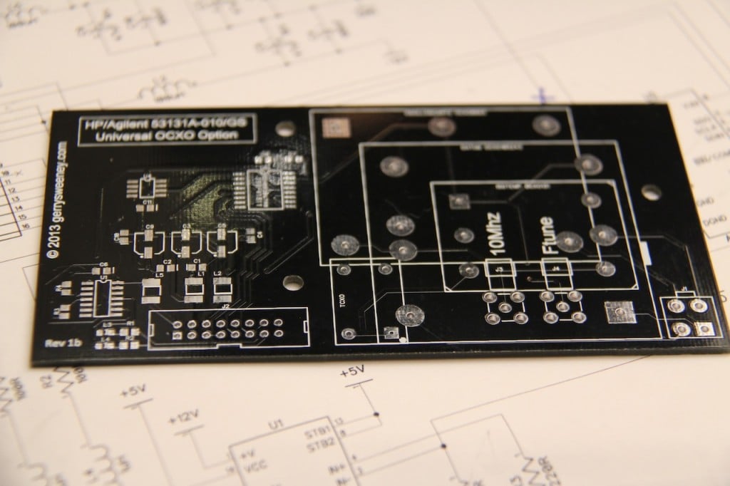
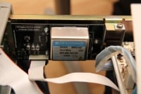
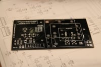
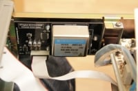
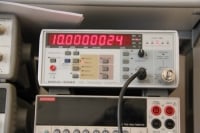
Having obtained a reasonably reliable 10MHz lab reference (see here) I decided to calibrate my Frequency Counter only to find that the stock oscillator provided in the HP 53151A is absolutely terrible – a joke even! I looked around for an “010 High Stability Timebase Option” but they are rare — and if you can find one not installed in a counter they are very expensive – in the few hundred dollars range at least — and buying one from HP is, well, expensive in the extreme. There are many second-hand 10MHz OCXO modules available, these are mostly stripped from old telecommunications, satellite or cellular equipment so they are plentiful and relatively cheap to buy too. I decided to make a clone 010 option board for my counter using a second-hand OCXO bought from e-bay. I designed a PCB to get a professional finish as well as a reliable upgrade for my counter. The main goal was to make an option board that just like the original could be automatically calibrated using the internal software and front panel controls so I had to use the same DAC chip (which is now obsolete) and basic topology of the original option board to make it work.

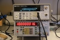
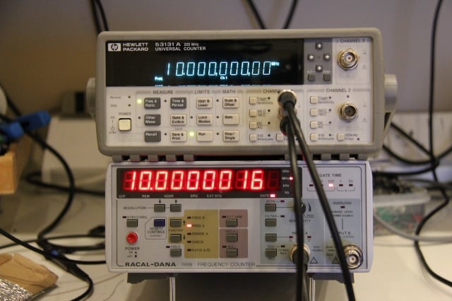
The result speaks for its self – with the OCXO running as the timebase, the counter is able to measure the 10MHz source it was calibrated with to a precision of 100th of one cycle with no error!

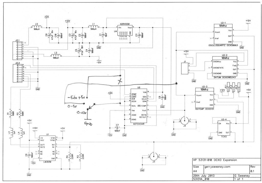
The schematic is pretty simple and self-explainatory. The counter seems to need a differential square wave clock drive, this is created using a high-speed differential output comparator part LM361. The DAC is an AD7243 part from Analog Devices, this part is now obsolete and not recommended for new designs but they are still available from various sources, albeit quite expensive parts. It would have been possible to design in a newer part but for the small number of units I wanted to make, it seemed a bit pointless to go to the effort as the recommended newer part actually requires different serial signaling, and this would have required some kind of serial protocol converter microcontroller. The DAC is driven by the counters microprocessor to calibrate and tune the timebase. The ADR4550 provides a high stability 5V reference for the ADC. The rest of the circuitry is basically power supply and signal filtering.

The PCB layout was designed to accommodate different OCXO footprints making it flexible. As well as supporting OCXO’s there are footprints for SMA connectors and you can even use a low-cost TCXO which cannot be automatically calibrated but is still a considerably better option than the oscillator built into the counter.

PCB’s Available : See here

The finished board fits really neatly inside the counter, and even fits around my previous Hard Power Switch Modification project.

Various Pictures

IMG_6028.JPG
IMG_6028.JPG
IMG_6026.JPG
IMG_6026.JPG
IMG_6031.JPG
IMG_6031.JPG
IMG_6034.JPG
IMG_6034.JPG
IMG_6024.JPG
IMG_6024.JPG
IMG_6038.JPG
IMG_6038.JPG

Catch you next time….

Five Decade Programmable Capacitor – A Low Cost Solution

As a follow-up to a previous blog post where I created a seven decade programmable resistor substation for use during electronic circuit prototyping and development, I thought I would expand on the concept and develop a decade capacitor solution to complement the decade resistor board. This new board is a five decade programmable capacitance and is in exactly the same form factor as the previous resistor project. The capacitance can be programmed in the range of 100pF through 9.9999uF in 1000pF increments. The tolerance of the capacitance is five (5%) percent.

My goal was to keep costs down while making the board usable and functional and reliable so I continued to use the 0.1″ jumpers I had used for the resistor board. However, to achieve a programmable capacitance you need to use small capacitors and parallel them to obtain the desired value, and the challenge here was how to achieve that with jumpers. In the end I took the simple approach and provided 10 jumpers for each decade, but instead of a two-pin header row I used a three pin header row so each of the 10 jumpers has an “on” (1) or “off” (0) position. I concede that the board is slightly more difficult to use than the resistor board, and thats simply because of the number of jumpers – dialling in a value involves moving multiple jumpers per decade. However, with the cost to use high quality switches I felt that the infrequent nature of use for the board, it was a reasonable compromise both in terms of design theme consistency and cost.

When working on linear circuits, in particular around op amps, PSU’s and other circuitry that needs response tuning, having a decade capacitance to hand when prototyping is a very valuable tool – not for day to day use of course, but when you are doing that specific job that needs this, its worth its weight in gold.

If you are interested in one of these boards I have had a bunch of them made and am selling them. You can buy them on http://tindie.com or if you prefer on e-bay – simply search for “gerrysweeney” on either system to find the items.

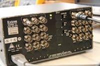
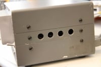
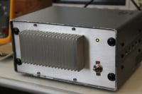
10MHz Rubidium Frequency Standard and Signal Distribution Amp Follow-Up

This is a follow-up to my previous article here. When testing the 1 PPS output I found some strange output which needed further investigation. I also decided to make further use of the microcontroller and status LED to indicate the 1 PPS signal to provide a degree of visual confidence that the frequency standard was working.

Various Pictures

IMG_5966.JPG
IMG_5966.JPG
IMG_5965.JPG
IMG_5965.JPG
IMG_5964.JPG
IMG_5964.JPG
IMG_5963.JPG
IMG_5963.JPG
IMG_5962.JPG
IMG_5962.JPG
IMG_5961.JPG
IMG_5961.JPG
IMG_5960.JPG
IMG_5960.JPG
IMG_5959.JPG
IMG_5959.JPG
IMG_5958.JPG
IMG_5958.JPG
IMG_5956.JPG
IMG_5956.JPG
IMG_5957.JPG
IMG_5957.JPG
IMG_5954.JPG
IMG_5954.JPG
IMG_5955.JPG
IMG_5955.JPG

The 1 PPS Channel
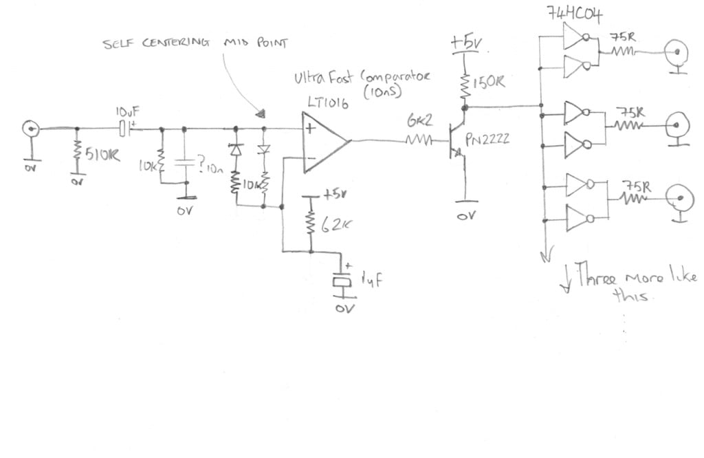
Here is the outline schematic of the digital channel of the video amp that is now used for the 1 PPS signal.

The fast comparator used in this circuit is an LT1016

The Micro-controller
When I first tried to implement this I used (or tried to use) the edge trigger interrupt capability which on the face of it should have been the perfect solution. However, no matter what I tried I could not get it to work, the best I managed to achieve was getting it to work some of the time, but it was very random. I suspect this was down to the way in which the PIC12X handles interrupts and context state saving implemented by the compiler, I read somewhere on the microchip forums that this issue *could* be resolved by upgrading to the PRO version of the compiler…..hmmmmmmm. Anyway, I decided to change tact and poll for the 1PPS signal which meant I also had to construct a really simple pulse stretcher circuit to ensure I was able to catch each pulse. Not as elegant as an interrupt-driven solution but it works. I think the more advanced PIC18Fxxx series micro controllers would have worked using interrupts but those are big chips and I was already committed to the PIC12F675.

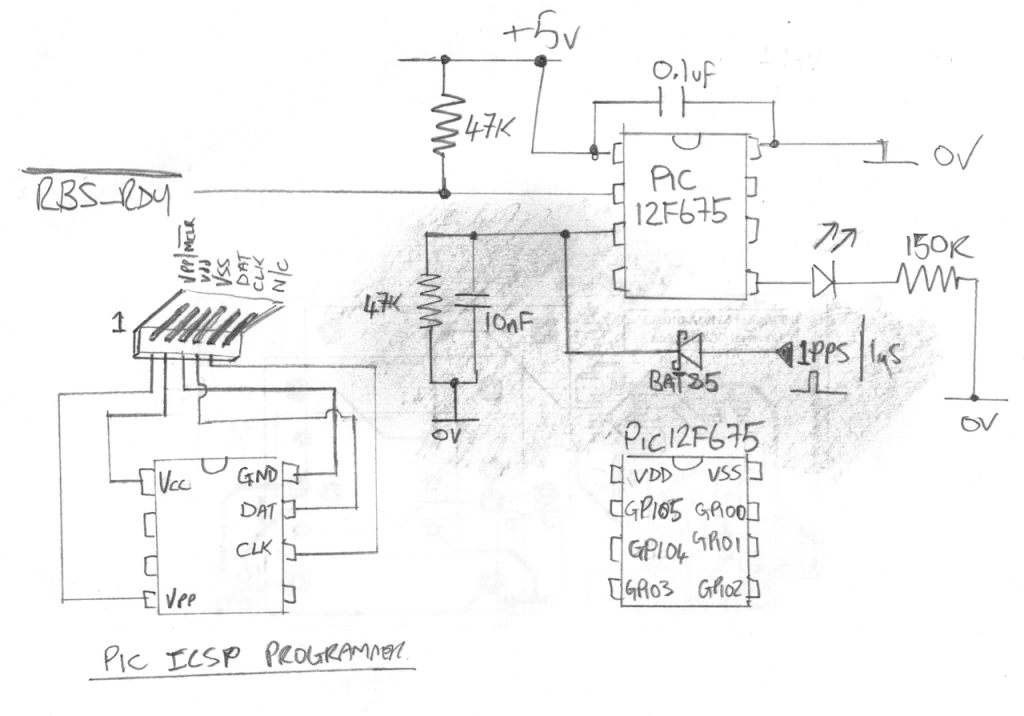
Here is the schematic for the micro controller which now also monitors the 1 PPS output of the RBS. The shaded area is what has been added to the circuit since the previous article.

Here is the firmware source code with the 1PPS implementation added. Its implemented as a simple state machine in run mode, I have tried to keep the code simple to read.

And for those of you that just want to program the chip, here is the compiled HEX file.

Catch you next time….