Build a 10MHz Rubidium Frequency Standard and Signal Distribution Amp for my Lab

Having gotten myself a Rubidium Frequency Standard I found that the unit on its own is not that useful, its really just a component and needs really a supporting PSU and a decent enclosure to make it useful. I was searching around for something suitable when I was directed to a robust quality unit being sold on e-bay for just £20 with an unbelievable level of re-usable content and turned out to be an almost perfect solution to making the Rubidium Standard a useful Lab item. Rarely does such a fine marriage of junk bits come together to make something really useful?

I had a lot to cover, the whole thing was built in an afternoon and as a result, this is a long video at 1 hour 16 mins so be prepared…

Video of the project build. 1hr 16mi

The PIC Micro-controller – PIC12F675
The original plan was to use the PIC for three functions, the first was to make the power LED flash while the RFS was warming up and on solid when locked. The second was to generate a 1 PPS signal from the 10Mhz signal and the third was to generate a PWM signal to control the fan speed. As it turns out the RFS already has a 1 PPS output on Pin 6 of the DB9 connector so there was no need for this. It also transpired that the only fan I had to hand was a three wire fixed speed fan, so I also did not need the PWM signal, this left me with just the power LED to deal with which is what the PIC ended up controlling. Here is the schematic for the PIC and the source code.

And the compiled HEX file if you want to just program the chip without compiling

The Video Amp – Extron ADA 6 300MX HV
The video amp unit I used in this hack is made by Extron and the model number (on the front panel) is ADA 6 300MX HV. When I communicated with the seller, he said he had about 30 of them, so if this is useful to you and you want to make your own I would go grab yourself one before they are gone. The basic outline schematic for an input channel is here:

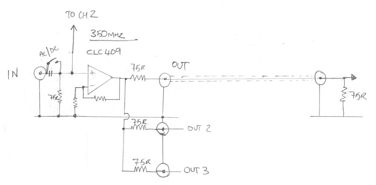
The video op amp chip used in this unit is a CLC409, the Texas Instruments CLC409 Data Sheet data sheet is attached to this article.

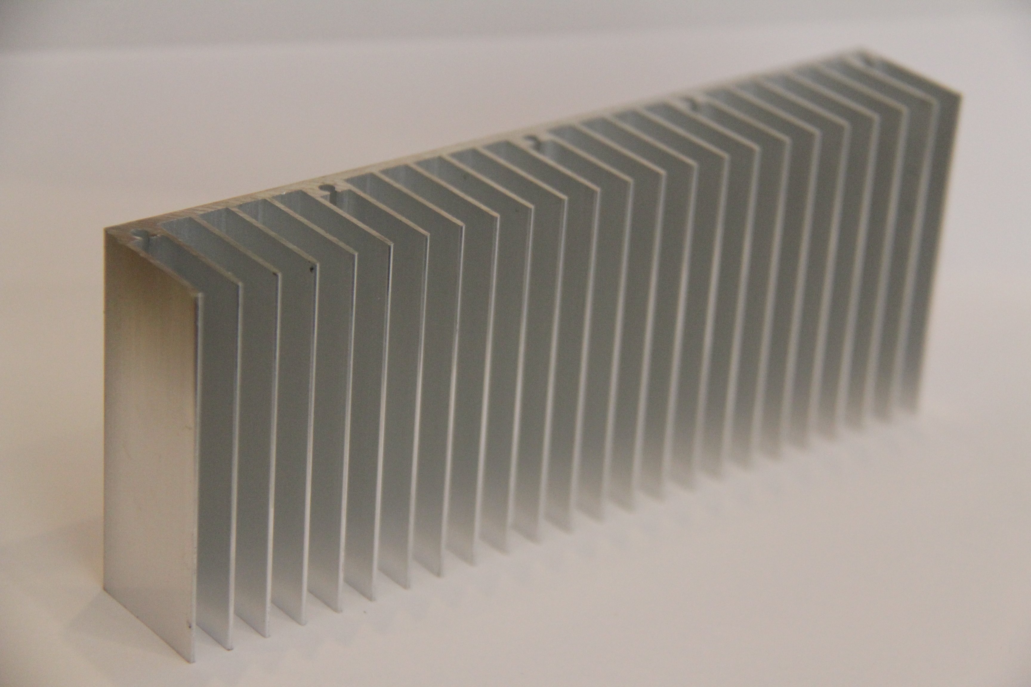
The heat sink I have ordered can be found on e-bay, search for “150x25x60mm Aluminum Heat Sink for LED”.

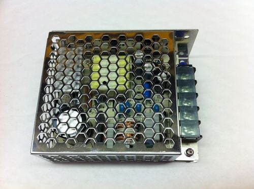
The switch mode PSU I used can also be found on e-bay, search for “Enclosed Power Supply SMPS,15V,2.4A,36W, it is made by TDK-Lambda and the part number is LS35-15”

See you next time.

DIY HP/Agilent 53131A-030 3GHz Channel 3 Option Board

As part of the process of upgrading my counter to have a DIY high stability OCXO (Oven Controlled Crystal Oscillator), someone who watched my videos had designed a DIY 3GHz Channel 3 53131A-030 option board. The original from Agilent is very expensive (obviously) and there are clones you can get on e-bay which are a quarter of the price Agilent charge which is why he decided to design his own. His name is Andy and when he saw my video’s he got in touch and offered me one of the PCB’s to which I of course said YES PLEASE 🙂

Now as it turned out, when Andy constructed his own board he had enough components left over so also constructed and tested one for me which was a really kind thing to do and very unexpected too. In exchange for this I have insisted that I can build him an OCXO board while I am doing mine to return the favour.

Anyways, I thought I would do a video to show the HP/Agilent 53131A-030 DIY 3GHz Cannel 3 Option board getting fitted to my counter. I also spend some time explaining how the pre-scaller circuit works and in basic terms what MMIC’s are and how they work too. I also make an adaption to my previous hard power switch modification to make way for the upcoming DIY OCXO board, and I measure up to get the exact board dimensions and mounting hole positions I need for the OCXO PCB layout.

The entire work and full attribution for the DIY 030 option board/PCB goes to Andy, so Andy – thank you so much for making one of these for me – I really appreciate it.

PLEASE NOTE: I will not put Andy’s Youtube/EEVblog ID here unless he asks me to, and I will not pass on his details without his express permission so please don’t ask – I respect people’s privacy. If Andy does want to share his details in connection with this project then I will gladly put them here.

PLEASE ALSO NOTE: The schematic drawing below is technically incomplete and is meant as an illustrative block diagram. In the real circuit there is also a resistor in series with each inductor at the top of each MMIC to set up the right DC conditions.

See you next time.

HP 339A Teardown

A piece of equipment I use rarely but when I do I find really useful is my HP 339A Distortion Measurement Set. Built in the 70’s this unit has a precision sine wave oscillator and distortion measurement section. One of the things thats really nice is the oscillator and the notch filter are tied together and the notch filter auto-nulls to make measurements really easy to accomplish.

The build quality of this unit is impeccable, made by HP when they were making stuff properly. The entire chassis is made from folded high quality aluminium sheets with capture nuts and really precise machining. The main oscillator switches are coupled using a bar and wafer scheme but both the oscillator and the filter are fully screened and isolated in their own chassis sub-sections. The smell from inside the unit is that old-school electronics smell I used to encounter all the time when I was a kid taking apart old TV’s and Record Players. I don’t know what chemicals exactly make that smell but I am pretty sure if you could bottle it you could sell it – there is an idea for a unique aftershave! It could be called “Ye’old TV Man”!

Anyway, hope you will find the video interesting. Thanks for watching.

Measuring Distortion with a HP 339A and a Keithley 2015 THD

I have had my HP 339A for a long time now and despite only using it a small handful of times it is a really great instrument – but – its big and takes up a lot of shelf space. A few weeks back a purchased a Keithley 2015 THD which is a 6.5 digit bench meter with a built in distortion analyzer, I bought it because of the distortion analyzer function. I would like to get some more instrument shelf space back so am able to replace the HP 339 with this 2015THD I will make that much-needed space. I decided to build a simple output circuit so that I can induce some crossover distortion and compare the basic measurements on these two devices to see the results. Now I must make it clear that this is a basic 101 on measuring distortion, I am sure there is a lot more to know that I do but I believe I cover off the basis.

The simple drawing I used to explain the test and test circuit.

I will tear down the HP 339A on video to show how nicely these are built. This is one of those rare “all analog” devices that has not digital parts at all, watch out for that video if you like seeing the guts of nicely built equipment.

Thanks for watching.

Seven Decade Programmable Resistor – A Low Cost Solution

I have spent a lot of time over the years prototyping electronic circuits and the amount of resistors that have ended up in the trash because they are so cheap you don’t bother to keep them tidy or organised once you take them out of their organised storage – you know the story. One potential solution to this is a programmable resistance box but the problem with these things are they are bulky and expensive and do not lend themselves well to breadboard prototyping. The cost of construction means they are typically the reserve of high-precision resistance boxes. I have a CROPICO RBB6E resistance box in my lab which I open up to have a look inside, its really well made, mostly by hand too, far too nice to abuse in prototyping….

I looked around at what is available but did not find a solution that met my own requirements so I decided to design something simple myself. I also wanted to make a simple project to get manufactured by machine which apart from other things requires reasonable volume, and I thought this project would be useful enough to others that I should get some made and make them available.

Various Pictures

IMG_5847.JPG
IMG_5847.JPG
IMG_5850.JPG
IMG_5850.JPG
IMG_5851.JPG
IMG_5851.JPG
IMG_5852.JPG
IMG_5852.JPG
IMG_5853.JPG
IMG_5853.JPG
IMG_5854.JPG
IMG_5854.JPG
IMG_5856.JPG
IMG_5856.JPG
IMG_5858.JPG
IMG_5858.JPG
00000273.png
00000273.png

Project Discussions

Project discussion thread on EEVBlog forums

Other Resources I mention in the Video

Cheap Resistance Substitution Box by @vtl on the EEVBlog
Cheap Resistance Substitution Box – Hack-a-day

If you do want one of these I have these for sale on “tindie.com”, the item listing is here:

https://www.tindie.com/products/gerrysweeney/seven-decade-programmable-resistor-1r-9999999r-1-500mw-gerrysweeneycom/

I have also listed these on e-bay, you can search for “gerrysweeney.com” which will find the listing.

As ever, if you have any comments, suggestions or feedback, please use the form at bottom of this page

Thanks for watching

I Need 10MHz – how hard can it be!

It all started when I wanted to calibrate my HP 53131A universal counter, which as it turns out probably has one of the crappiest and most disappointing standard oscillators ever put into a frequency counter, HP you should bow your head in shame….oh of course I forgot, a half reasonable oscillator is an “optional extra” when you by HP/Agilent – of course it is….anyway, on with the job at hand

If you have or want to play with an FE-5680A Rubidium Frequency Standard or an OSCILLOQUARTZ OCXO 8663-XS or a HP 53131A Counter or a Racal Dana 1999 counter or similar then this video will most likely be of interest 🙂 what I am trying to get is a predicable and reliable frequency and standard for my home lab.

I guess I will let the video do the talking on this one….

Here are a whole bunch of useful links that relate to this video (there are many more too if you search around the web)

Thanks to all of the authors and content creators for the above information. Thanks for watching.