Here I describe the basic operation and topology of a Class D amplifier and then tear down an Omnitronic 1000W amplifier to have a look and see what is inside. The big advantage of a Class D amplifier is the compactness and overall power efficiency. However, Class D amps are generally not used in High Fidelity application because of the limitations in dynamic range and distortion performance that can be achieved.
Here are the specifications scanned in from the user manual.
Hope the information is of some use. Thank you for watching.
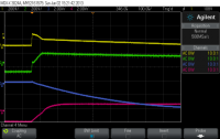
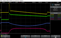
I said last time I would look at the software and firmware for this post but I decided I needed to spend more time on the regulator to address the DC response issues I had observed, I felt this was more important to get right so this article focuses on that. The good news is, I have achieved good results and I believe the regulator design is complete – at least for the high current version of the module (0-8V 0-8A).
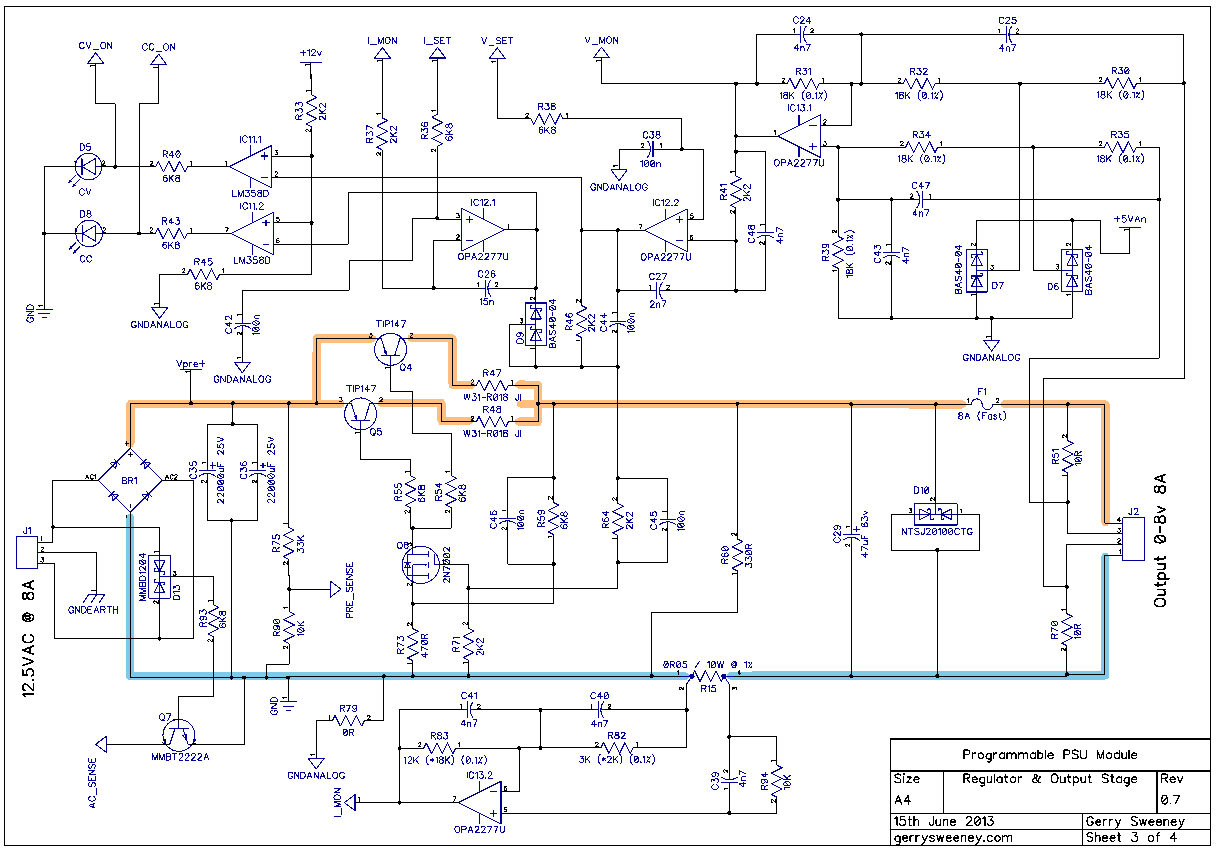
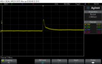
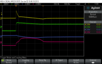
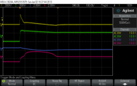
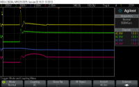
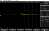
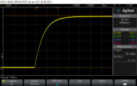
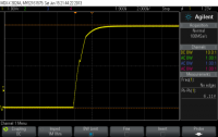
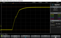
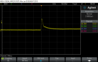
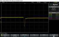
I had problems with the regulator over shooting by about 500mV when transitioning from a high power load to a low power load. There were two main problems, the first was down to the inductance of the wiring on the output, that creates a problem which in turn was amplified by the relatively slow response of the various amplifier stages. I have achieved significant improvement on my previous measurements by tuning response times through the various stages, this simply required lowing the impedance through the various stages to ensure the servo was able to respond more quickly to changes on the output. This was achieved by adding C24, C25, C39, C40, C41, C43, C45, C46, C47 and C48 to the input and driver stages. I also needed to throttle back the fast rise time of the control drive from the DAC to follow behind the response curve of the regulator circuit. These changes mean the regulator now delivers a clean and very acceptable dynamic response to fast-switching load conditions.
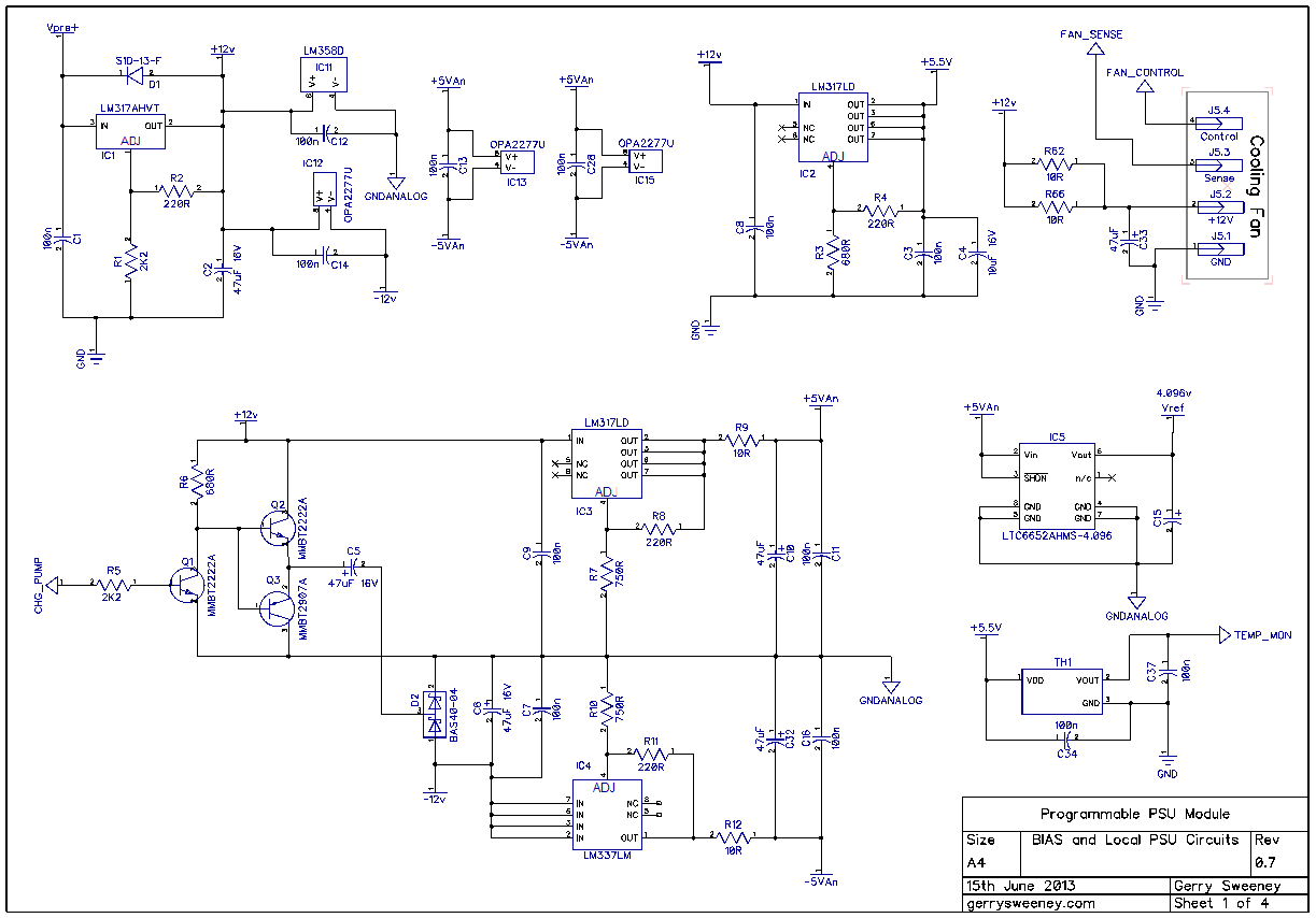
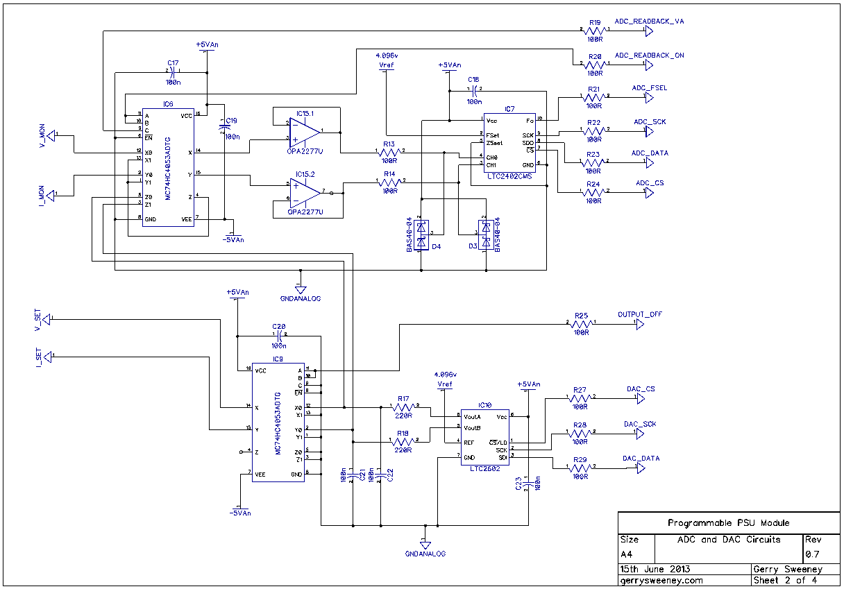
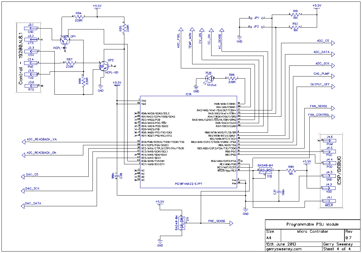
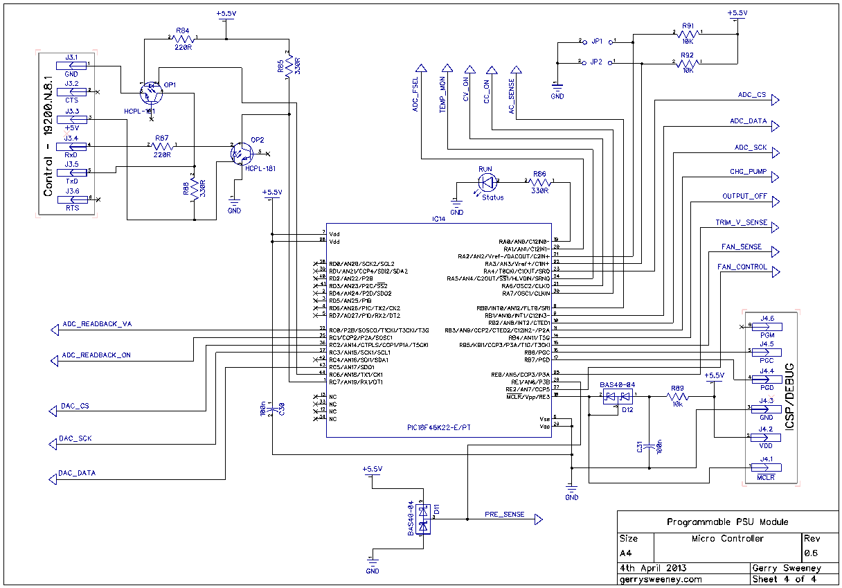
The Schematic
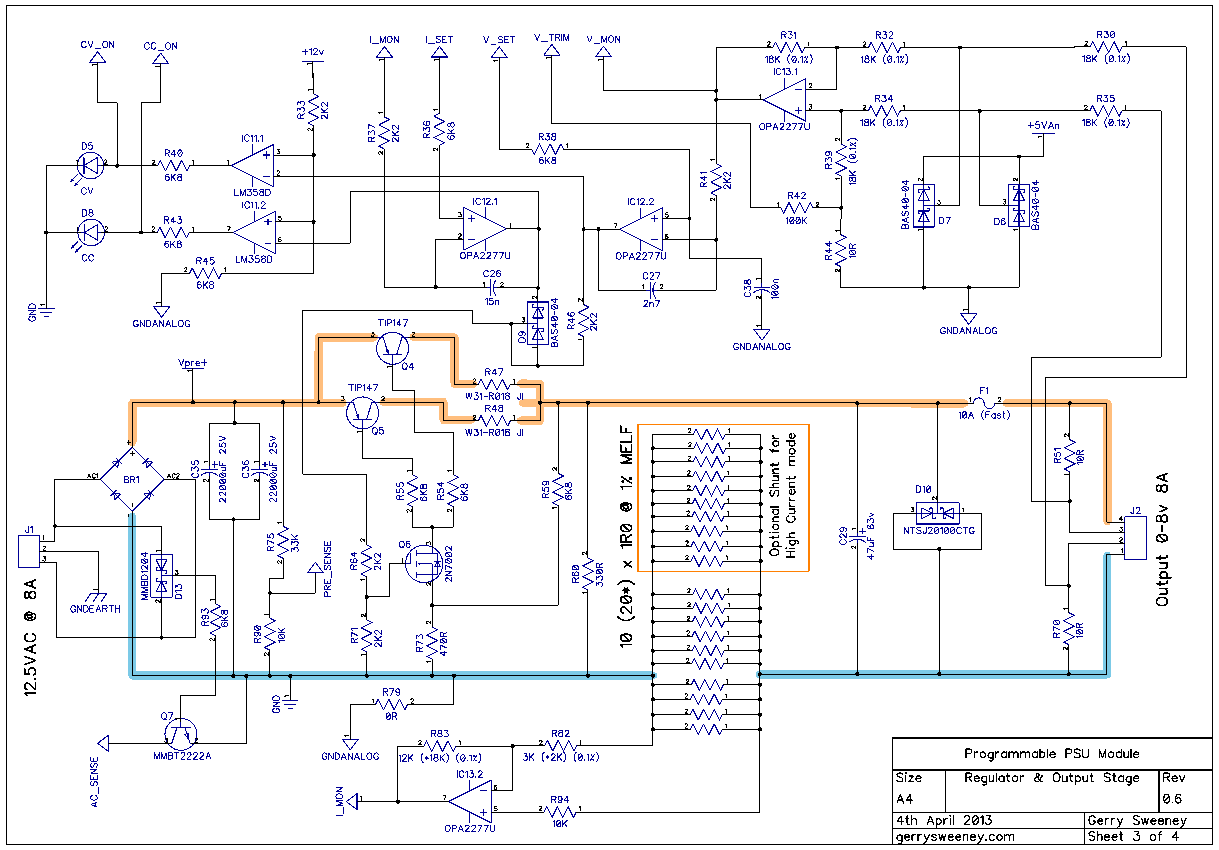
Here is the latest schematic which is at version 0.7 including all of the latest changes. The most significant changes are on sheet 3.
I now need to lay out the new PCB and get some ordered, I will do this over the next couple of weeks. I will definitely cover the development environment and the firmware in the next post as well as the serial protocol used to control and monitor the module.
Following on from my previous post in relation to the HP 53131A Frequency Counter Teardown I have devised a reversible modification that replaces its soft power switch (where the switch mode PSU and the fan are running continuously when the unit is plugged into the wall outlet) to a hard power switch which properly turns the unit off from the front panel. The modification is simple to do, uses inexpensive parts and is completely invisible, it looks and feels like factory behaviour. It is will worth applying if you have one of these for bench use so you can leave it plugged into the wall without having the fan running and switch mode noise being generated when the unit is not in use. It’s hard to understand why HP did not include a hard power switch in the original design, you will see from my modification there is plenty of room, and it seems such an obvious thing to do. Anyway, I have created a video showing the details of the modification, if you have one of these frequency counters I hope you find the modification interesting and/or useful.
UPDATE: Having re-read the schematic again it appears that the unswitched +/-12v from the switch mode PSU are provided on the OCXO option connector J9. This would explain the design approach, the PSU will run the xtal oven even when switched off so when you are ready to use it, its instantly available. Thats fair enough except that many of these counters exist that do not have an OCXO option, and even with one fitted, I personally would be happy to know I have to switch it on in advance of using it.
NOTE: Please forgive the under-exposure on the first part of the video and the audio noise in a few places through it, I have a new camera setup and am getting used to it. The audio noise I believe comes from the phantom power not being liked by the wireless mic (I hope its that at least). The under-exposiure is just my misinterpretation of the zebra exposure indicator, you will see I get it right (or at least much better) in the second half of the video.
One of the instruments I have is a HP 53131A Frequency Counter, and putting the positives of this unit aside, its by far the most annoying bit of test gear I have! Why? well for some reason, when you apply power to the thing the fan runs even when its switched off. This is because the power switch is a soft switch and with just the AC cord plugged in the fan runs and makes the annoying fan noise. This is a really poor design and certainly not one of HP’s shining examples of engineering….I like to be able to switch my stuff off without reaching around the back and having to pull the power chord or unplug from the wall outlet – just plain crappy! HP what where you thinking?
I thought I would tear it down and have a look and see why this is, and perhaps see if there is any possible modification I could come up with to improve on this. When I took it apart I found a real mess of dust and some kind of substance spillage so a full clean-up was needed which somewhat distracted me from the power switch problem.
While its in bits, I also do a quick run through of the major components of the circuit and have a quick look at the power supply and power switch circuits in some detail.
UPDATE: The clean-up also appears to have resolved the strange trigger problems I had seen previously with this counter. Well pleased…
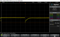
It’s taken me a while since the last update, I have been real busy of late. Having completed the first physical build, I now need to make various changes to the construction. Given the screw-up of the star earthing topology on the first board, I need to layout another board revision so I am going to make a bunch of other improvements. In this article I cover the various design changes and perform some basic power, DC condition and regulator response tests, I identify and resolve some issues and re-select better performing op-amps as an alternative to the LT1013, I have selected the OPA2277U part, and I have also tweaked the power supply implementation for the drive circuitry to reflect the fact that the newly specified op-amp is not a single-supply rated part.
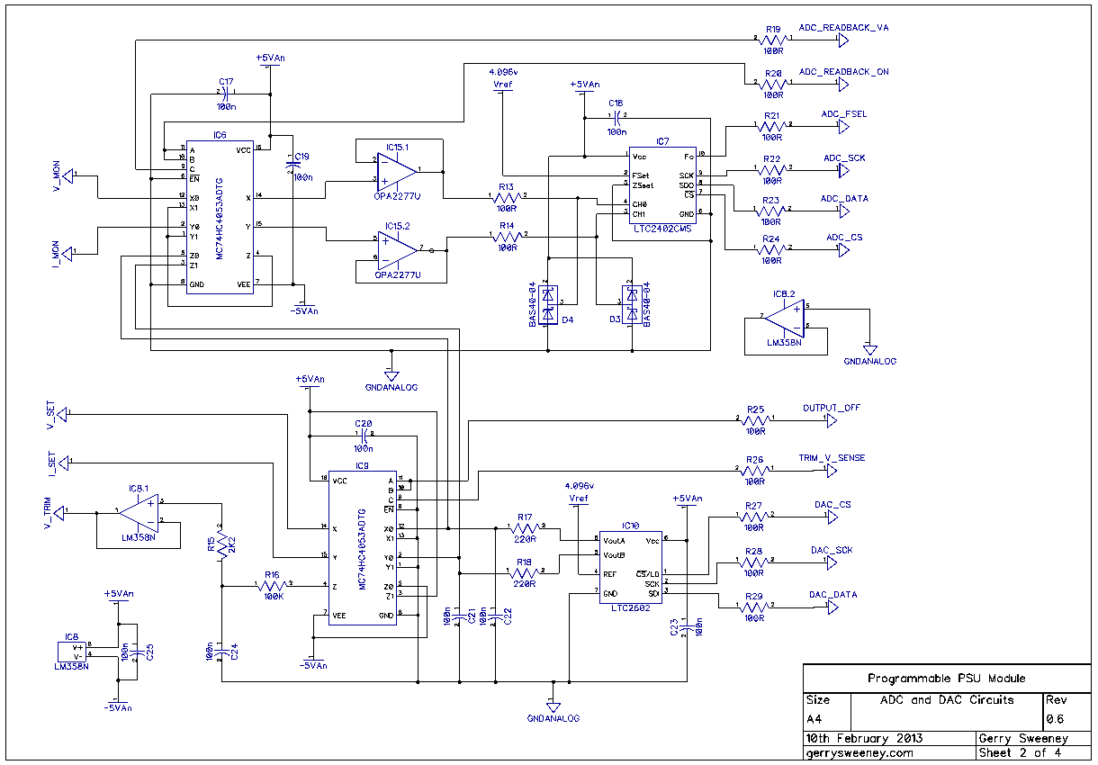
The Schematic
Here are the latest schematic which is at version 0.6 including all of the latest changes.
I now need to test and resolve (or decide its acceptable) the overshoot problem when testing the load/no load dynamic response of regulator. I also need to re-layout the next board revision, get some boards made and build the next version. In Part 14 I am going to cover the firmware, describe the development environment and show the basic software layout as well as details on the current serial protocol I am using to control the module.
Thank you for your continued interest in this project, please give the video a thumbs up if you have found it interesting.
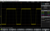
This is a short follow-up to a video where I was recently testing a Mayyuo M9711 DC Electronic Load (See Here) and I was using an Agilent E3634A Power Supply (which I previously fixed) as a power source. When I put the DC load into pulse mode within a few seconds the E3634A PSU exploded. What I heard was a loud pop, and a flash followed by a loud vibrating 50Hz hum, by which time I was able to reach the power switch and shut it down. I switched to another supply and continued with the test of the M9711 but today I thought I would open up (once agin) the E3634A and see what damage was done and what I found is a real mystery!
Did I imagine it all? Was there beer involved? Who knows, its a mystery!
Hope you enjoyed the video, catch you next time…
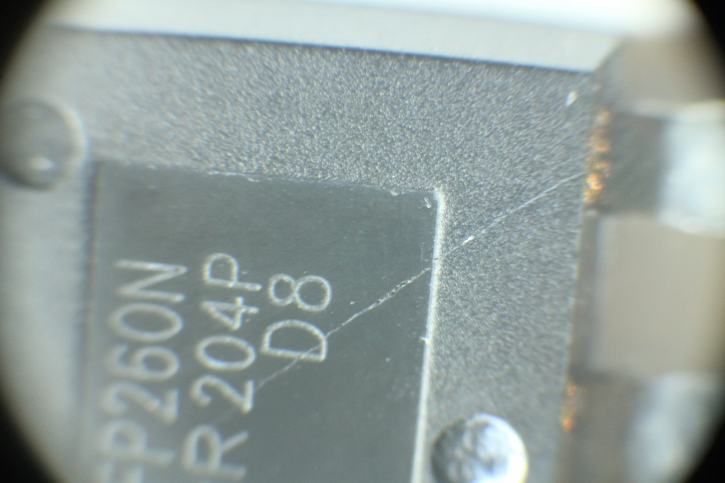
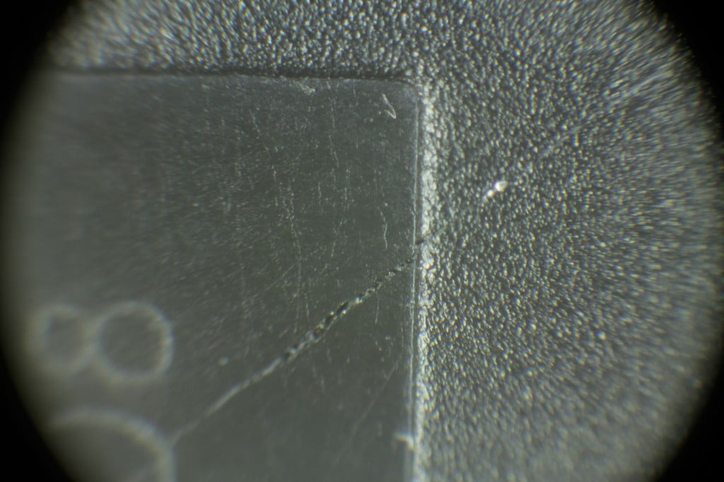
UPDATE – I found the smoke source
While tidying up I thought i would have a look at the two power MOSFET’s that failed and found the IRFP260 has a very small but visible smoke vent! I have added the photo’s below, I had to take these under the microscope x10 and x30 to see it. With the naked eye it looks like a light scratch.