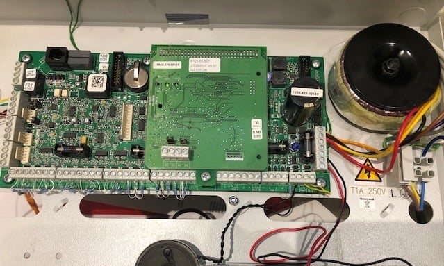
I recently replaced my current intruder alarm system with a Galaxy Dimension G3-520. These alarm systems are quite advanced, professional intruder alarm systems made by Honeywell and from hardware design and overall architecture are most definitely on the professional end of the scale. On the second-hand market (aka e-bay) they are not very expensive and are still relatively modern systems.
This is also a very “hackable” system making it friendly for DIY’ers and IoT systems and experiments and stuff. I do plan to write some other, possibly more interesting articles about this system and its overall hackability, but I thought I would start with a simple one, the mains transformer – which actually sucks! Here is why…
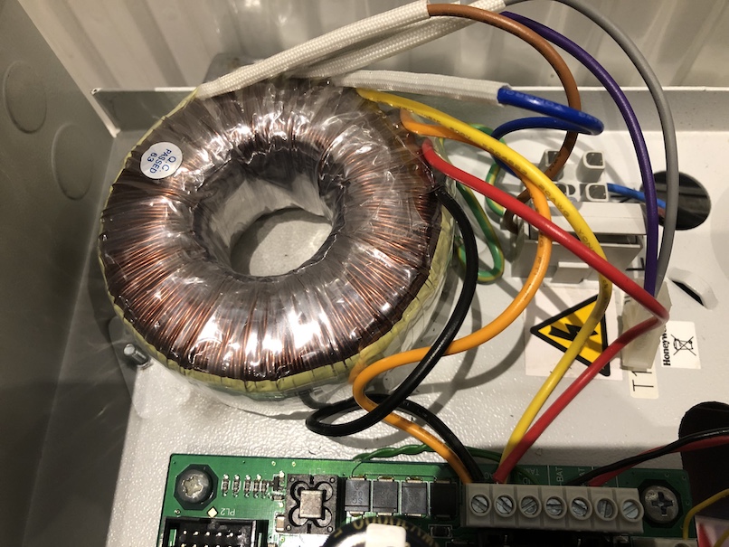
One of my first observations when running the panel on my desk was how hot the mains transformer was running. I measured it at around 55 degrees Celcius. Now with the lid on, and with the panel installed in an enclosed space, this is not ideal. It was getting hot enough that I thought there was something wrong with the transformer. I bought a second panel and transformer, and low and behold the transformer was just as bad.
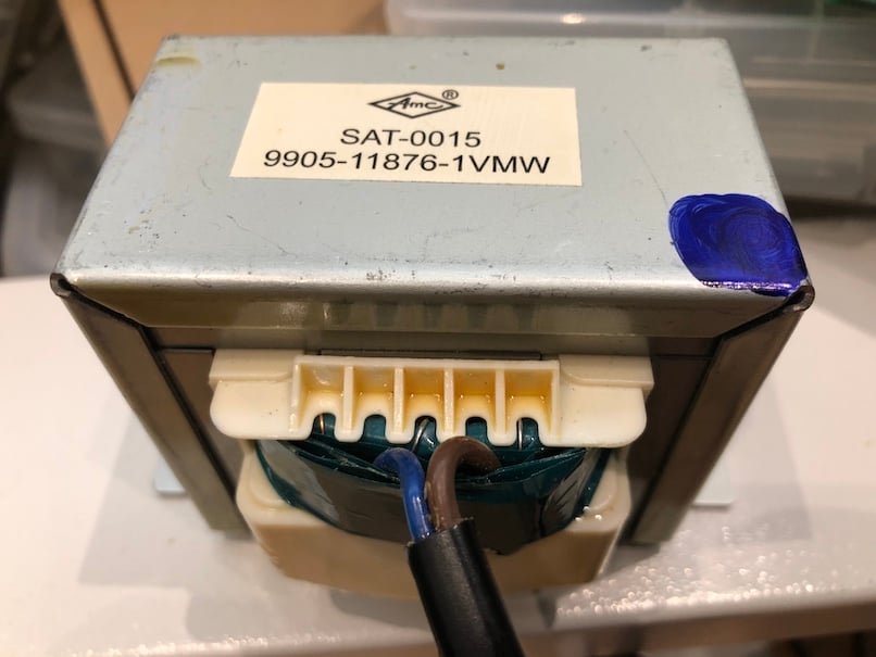
Looks and feels good quality, but performs quite badly
The transformer is an Iron Core transformer, typical construction that most people are familiar with, and these types of transformers are known to have some inherent inefficiencies. The quality of the design and construction of the transformer play a big part in how efficiently the transformer performs.
There are two sources of loss in a transformer. The first is known as load loss and is as a direct result of resistance in the copper wire that makes up the transformer windings. Cheap copper alloys have higher resistance generally, as you draw current through the wire, heat is generated as a result of the resistance in that wire. The second source of loss is Core Loss, which is where the transformer consumes power it’s self, even when no load is present. The heat generation is caused primarily by resistance in the iron core of the transformer. The transformer in this panel suffers from both problems quite severely, its a poor quality transformer.
I did not want to install the panel with this heat-generating cheap-ass transformer, so I decided to fix it. I had two options, replace with a Switchmode or replace with a better quality passive transformer. Switchmode PSU’s are excellent for high power levels and small spaces, but they do suffer from power losses too. Moreover, there is the question of long-term reliability which I feel would be a problem for this application; there is nothing so simple and reliable as a transformer.
So to fix this in my panel, I have replaced the transformer with a toroidal type. Toroidal transformers are a better design and inherently have much lower core losses than a more traditional transformer. A good quality toroidal transformer should also not suffer load losses if they are correctly rated.
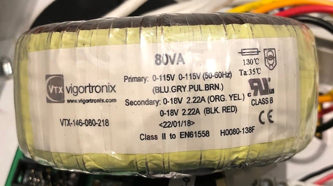
VTX-146-080-218 Transformer 80VA 18VAC x 2
The panel is rated for 1.2A and 2.5A in its power and aux circuits, and needs to charge a Led Acid battery too, there are three 1A fuses and one 1.5A fuse on the board. So the power consumption of the panel and the accessories it can power from Aux 1 and Aux 2 totals about 44 watts (3.7A * 12V), and then you need at least another 18W to charge the standby battery so we are up to 63 watts of power. To give me about 20% headroom, I chose a transformer rated at 80W. Its an 80VA 18-0-18VAC secondary transformer made by a company called Vigortronix, part number VTX-146-080-218. You can get this from Farnell, or as I did, from an e-bay seller called Spiratronics, It cost me £23.50 shipped and included the mounting kit needed for a simple installation.
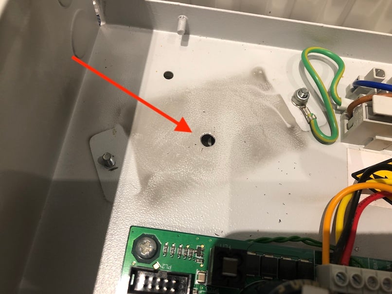
Drill a 5mm hole, and deburr. Make sure no metal fillings are left inside
To fit the new transformer was as simple as drilling a hole in the right place, making sure the transformer does not hit the two studs that fixed the old transformer to the chassis and wiring the transformer. Wiring is dead simple, see the image below.
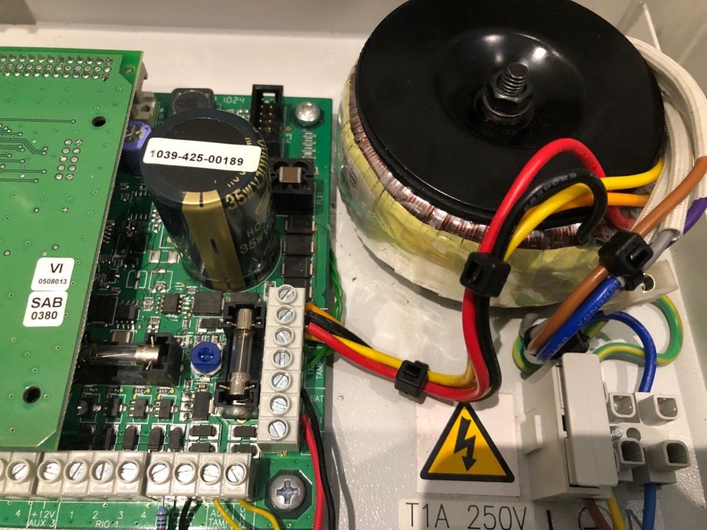
Wiring up before bolting down
Primary side, you need the two windings in series for UK/EU and parallel for the US. For the UK, connect the grey and purple wires and insulate, connect the brown and blue to the (L)live and (N)neutral respectively. Secondary side, you need the two windings in parallel, so connect black and orange into one of the AC terminals on the PCB and connect the Red and Yellow wires and into the other AC terminal on the PCB.
Transformer installed and wired ready to go
The result. A transformer that does not get hot at all; it’s cold to touch after a week of running the panel and some attached peripherals. I have not measured it precisely (I may well do that at some point for the academic exercise), but basic measurements suggest there was around 3W of power loss in the old transformer with barely any load, that would be around £5/year in energy being wasted, not much but not trivial either. The significant benefit for me is that the panel is no longer generating the kind of heat that can build up in a closed space, its comforting to know that energy is not being wasted too and overall it just feels better, the transformer is no longer “just good enough.” its now correctly specified and just feels more professional.
I have been an Apple desktop user pretty much ever since they moved to the Intel architecture and I have been pretty pleased with my Apple computers. Unlike the bad experience I had with Windows and PC’s the iMac and OSX have been really great for the sorts of things that I do all the time. More recently though the quality of the OSX updates have been less than perfect and its starting to feel a bit like Microsoft all over again with regular OS updates that need a computer re-boot – anyway, I digress…!
One of the computers I use at work is an iMac 27″ and a few months ago the screen backlight failed, first it flickered and then half the screen went dark. So I call Apple and explain the problem and because my computer was a few months out of warranty they said my only option was to take the computer into an Apple store where they will fix it but I will have to pay for the repair – I decided not to do that because it would mean being without the computer and I need my computer at work so I decided to live with the half dark screen.
While looking around the apple support community forums I found out recently that although Apple are staying tight-lipped about this problem it would appear that *alot* of people are having this exact same problem and Apple is charging £400+ a pop to repair it – by replacing the entire screen panel it would seem….the problem has been dubbed “The Dark Side Screen Problem”…
Over on the Apple support communty “Kaos2K” found the actual root cause of the problem which is actually a manufacturing fault although Apple has been refusing to admit it so far. The problem is, heat from the backlight/screen seems to cause a surface mount 6-pin connector to break away from the board its soldered too, the only explanation for this is a poor solder joint at the time of manufacture. The thread that describes the problem can be seen here: –
I accept that the fault probably lays with LG who make the actual panel but still Apple should be fighting the corner on behalf of their customers. I anticipate Apple loosing the case and are likely going to be compensating everyone who has had this problem.
Using the information “Kaos2K” posted I decided to make a video on fixing my iMac.
Having undertaken this repair I have absolutely no doubt that this fault is down to a manufacturing defect relating to the quality and specification of the soldering of the 6-pin connecter too the LED strip used as part of the backlight, there is no way that connector should simply “fall off” as it seems to be doing. Given Apple is the biggest technology company in the world and are so very proud of their hardware (as they should be) its is an utter disgrace that they have not recognised this problem and stood by their customers. With so much in the news last about how much cash Apple have its a shame that in a position like that they have decided not to stand up and take responsibility – shame on you Apple, its stuff like this that will drive your loyal customers back to Microsoft….
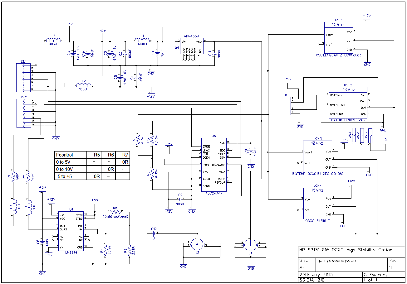
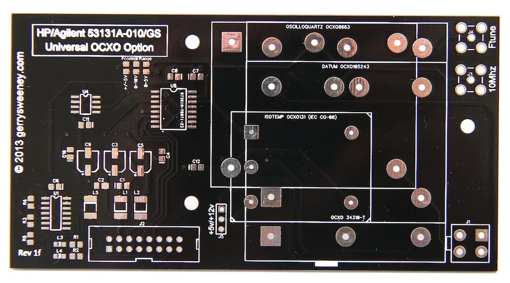
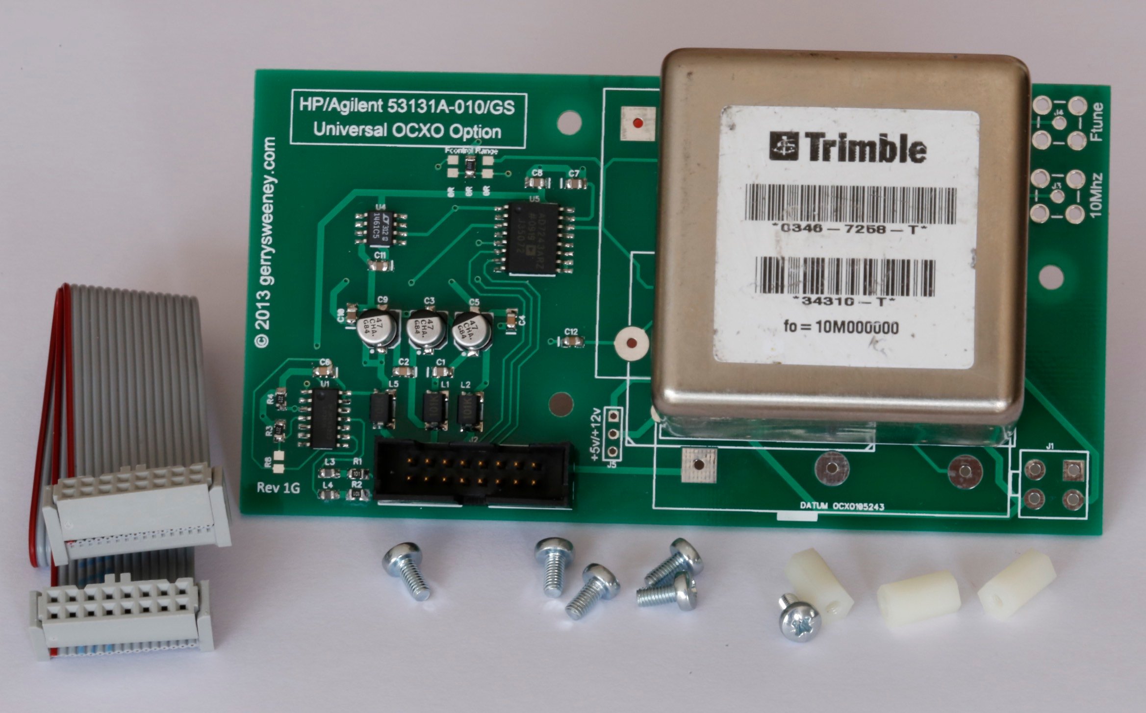
Following on from the project to build a DIY OCXO upgrade option for my HP/Agilent 53131A Frequency Counter I had a large number of requests for me to make the PCB’s available so others can built there own. I now have some PCB’s and are making them available for sale. I will also be making some fully assembled and tested/verified boards including an OCXO, ready-made cable and mounting stand-off’s, there will only be a limited number of these so if you are interested, let me know, first come first serve and when they are gone they are gone.
Now, someone made a comment on hackaday stating that the reason why these OCXO’s are on e-bay is because they are no good. Well I can understand why one could draw that conclusion but having now played with in access of 50 of these OCXO’s I can tell you that they all pretty much violently agree with each other and they also agree with the Rubidium Frequency Standard I have, so given they are from different sources and all free-running I am pretty comfortable they are good and usable quality devices. I read a lot on the net about “burn in time” and the general consensus seems to be, the longer you age and heat a crystal oscillator the more stable (in terms of drift) it becomes. Now I don’t know how true that is, but if it is true, then by definition, using recovered OCXO’s must actually be a good thing. Of course if you feel the need to pay a couple of hundred dollars for a new OCXO then you can of course do that – but I am pretty sure that it does NOT guarantee you any better performance, it just buys you the right to get compensated if you happen to find it does not meet the performance specifications quoted by the manufacturer and it might make you feel a little more confident. Anyway I guess the results speak for themselves and for a home lab these OCXO’s are more than good enough I think.
Here is a short video showing the various configurations built and working as well as a quick overview of the PCB its self and the configuration options.
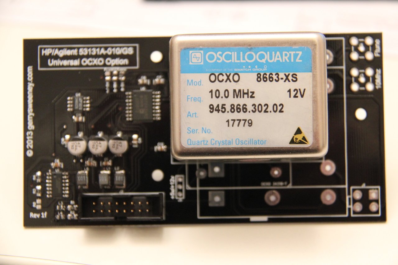
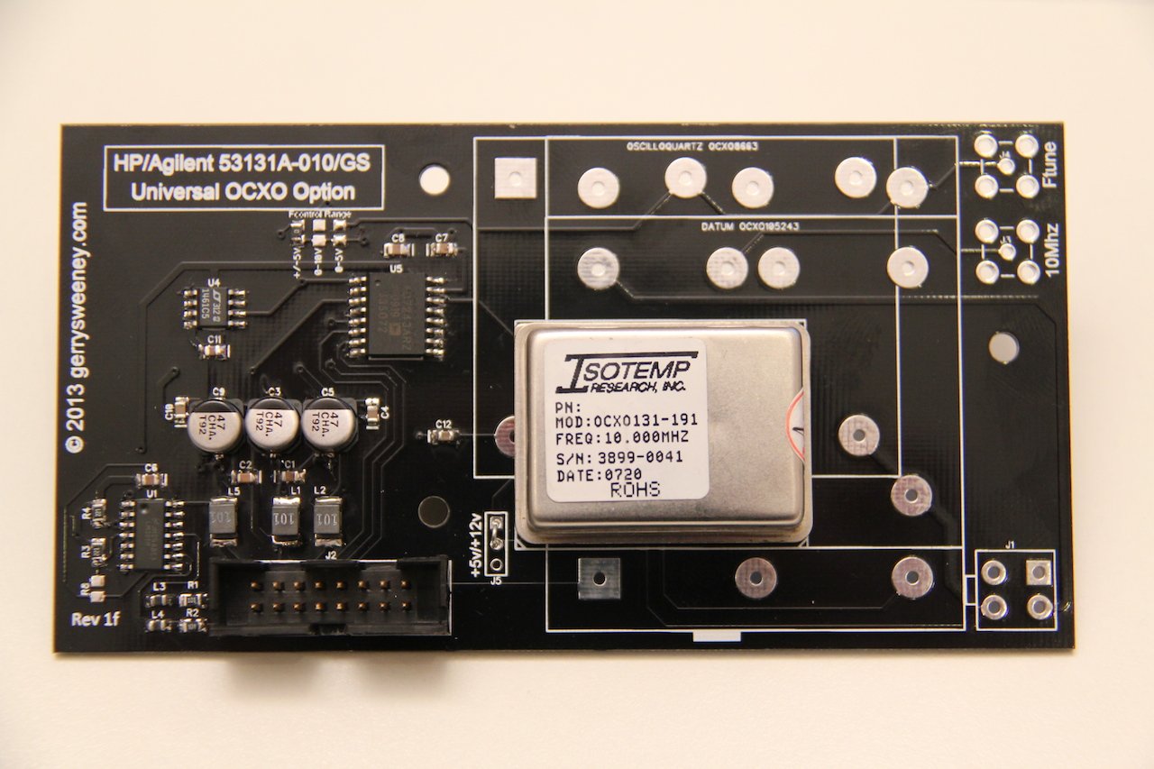
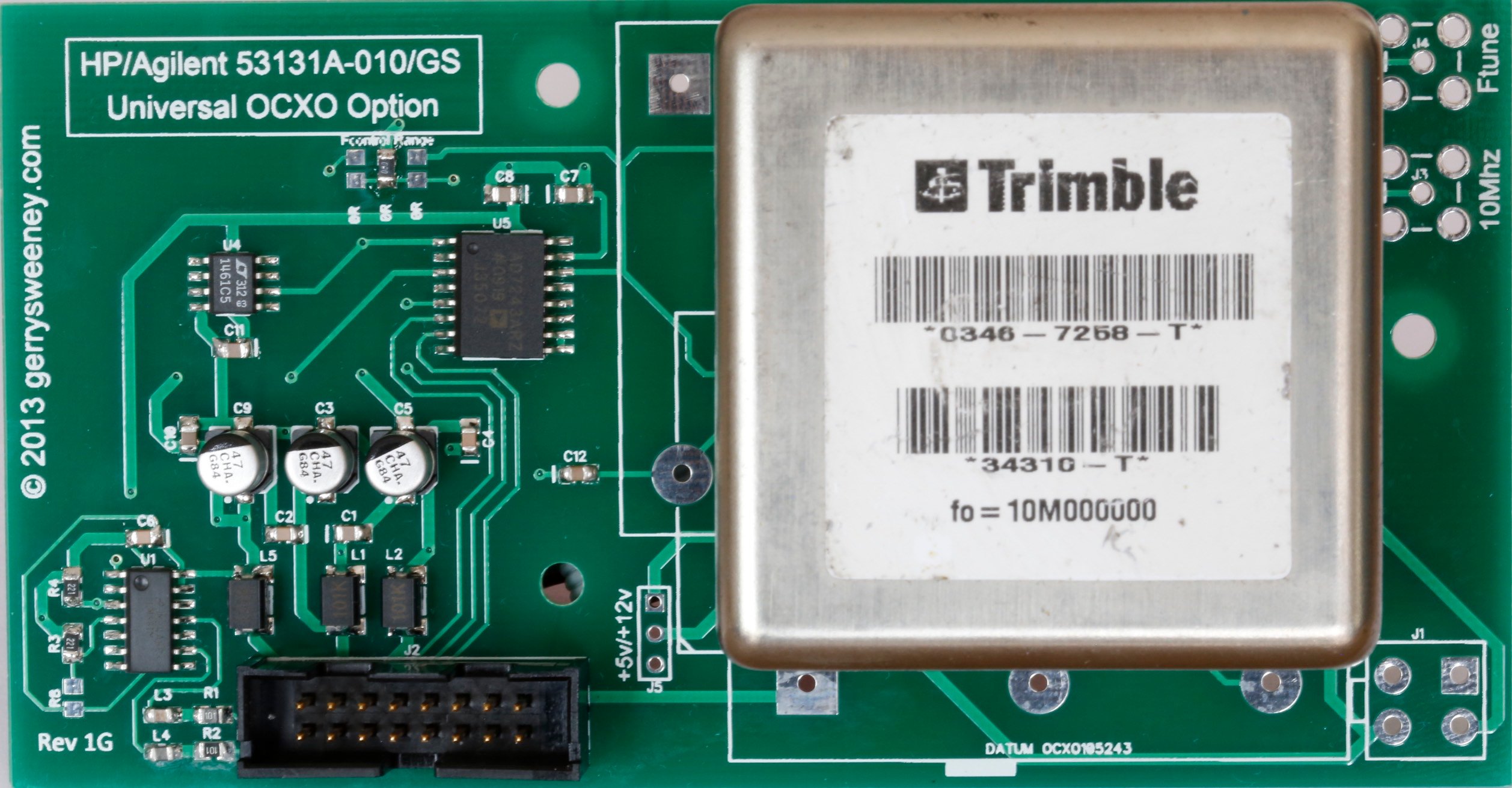
This is the revision “1F” board. When I designed the board, I picked a few of the OCXO types that are available on the second-hand (salvaged) market and designed it to accommodate these. My original plan was to support four types of OCXO, the Oscilloquartz 8663-XS that I used in my own counter, a Datum 105243-002, and Isotemp OCXO-131 and a Trimble 34310-T(2). However, when I laid the board out I did not have the Trimble 34310-T(2) device to hand and made a (wrong) assumption about the footprint – which is a bad schoolboy error I know – the upshot being that while this board has a footprint and markings for the Trimble 34310-T(2) it does not fit, the pins are about 1mm out and therefore the board IS NOT suitable for that particular device. It is feasible to drill holes, the pads are just about big enough but assuming there is some demand for these boards I will order a second batch with the footprint corrected.
The following OCXO’s are known (and shown in the video) to work. Any others might work but thats up to you to verify 🙂
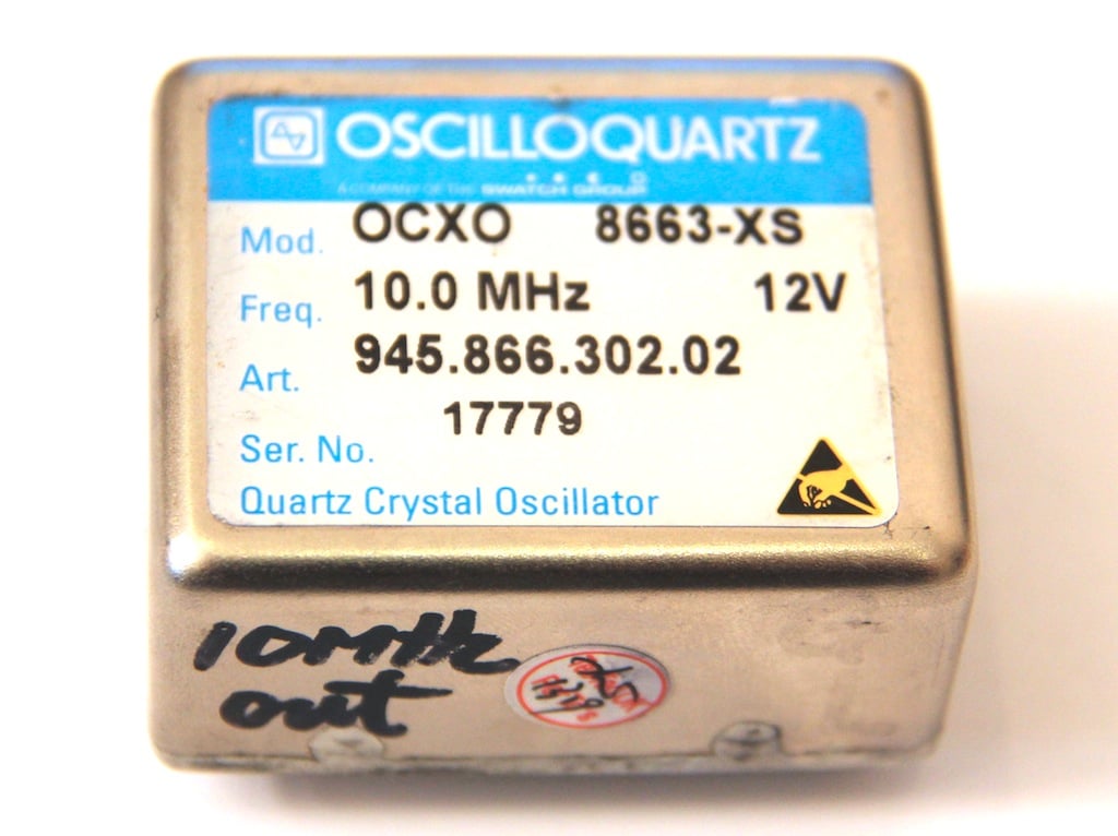
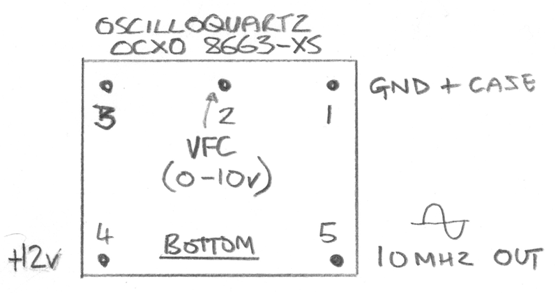
Oscilloquartz 8663-XS
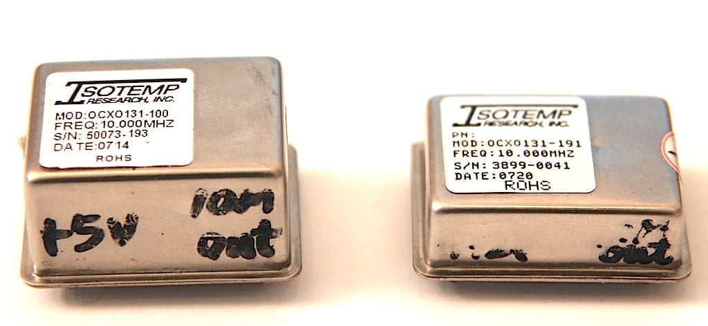
Isotemp OCXO131-100
Isotemp OCXO131-191
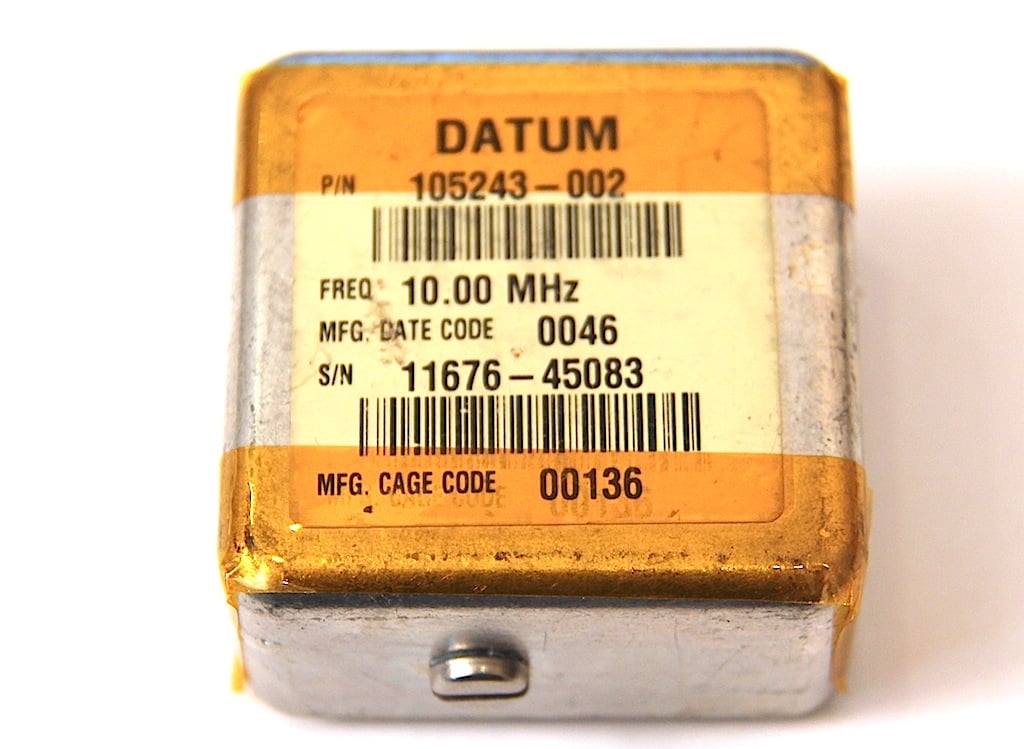
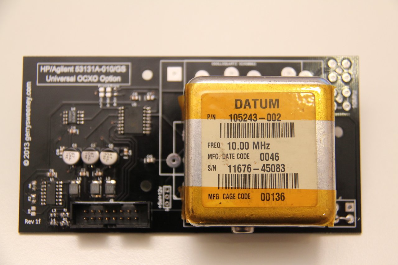
Datum 105243-002
Oscilloquartz 8663-XS
This is the first OCXO I used, its more expensive than most and seems good quality and very precise. It works off of 12v and provides a nice clean sine wave output. The voltage control input works on the 0-10V range. I could not find any data on the XS version so I don’t know what its performance specifications are. I have included a download for this device but it does not cover the XS version specifically. The data sheet states that this device requires 0-10v for the frequency control, and testing seems to bear this out too. However, to get the counter to calibrate properly I selected the 0-5v range on the DAC.
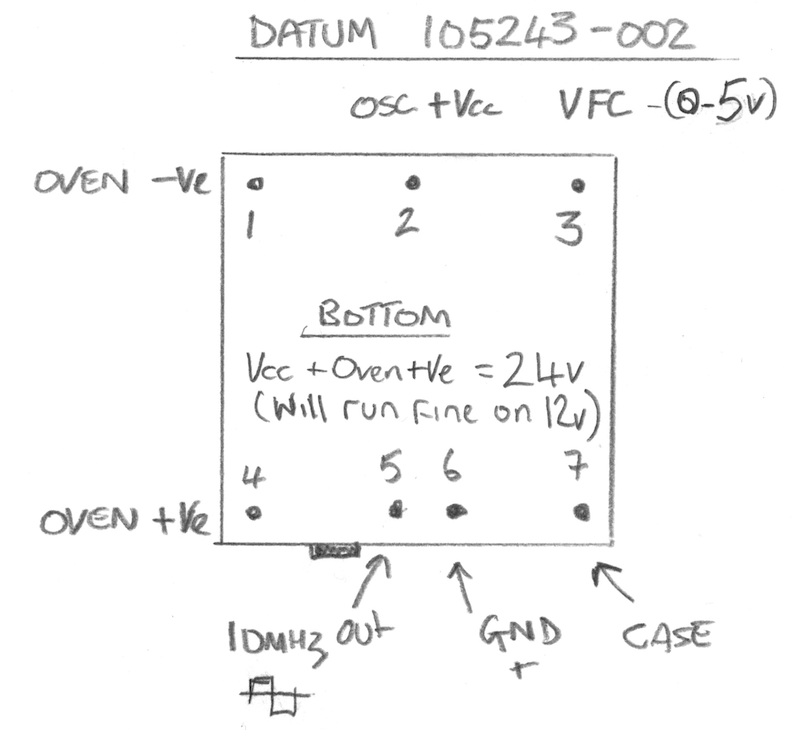
Datum 105243-002
This was another OCXO that I included on the board for Andy (who built the first 3Ghz pre-scaller option board), again a nice device but its specified to work on 24V and the Oven and Oscillator have separate power connections. This is the only OCXO that has a built in trim pot which allows you to set the window for the voltage control range. Although this device is specified to run at 24V, I tested its operation at 12V and it works perfectly. I did put a four-pin plug onto the board to allow you to give it a separate 24V supply but it really does not need it. I do not have any data sheet for this device but it outputs a square wave which is not as nice as having a sine wave on the output – but for this application it does not matter at all. The Frequency control input on this device is very sensitive and while it works without problem at +/-10v its centred around 2V and 0-5v works just fine.
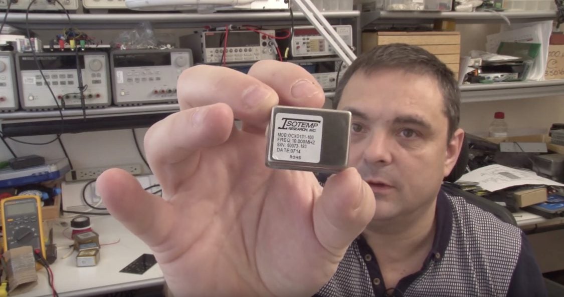
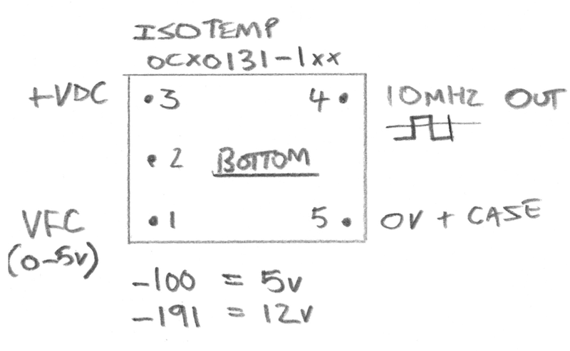
Isotemp OCXO131-1xx
This is a small, compact device and comes in two variants, the OCXO131-191 which is a 12V version and the OCXO131-100 which is a 5V version, and while both share the same PCB footprint and pinouts the case for the 5v variant is taller at 18mm high where as the 12v version is a compact 11mm high. These also provide a square wave output. Both versions of the device require 0-5v on the frequency control input although to get the counter to properly calibrate I had to configure it for the +/-5V option.
Kit of Parts
Some people asked me about providing a kit of parts. I am not really geared up to do that in a time-efficient way so apart from the bare PCB, I will not be able to provide individual parts or components.
Fully Built and Tested Option
I am planning to have a limited number of these option boards fully built and tested with all the components and the OCXO pre-installed as well as a suitable cable and mounting stand-off’s, ready to install and use in your counter 531xx HP counter. I do not have an exact cost for these as I still have to source some of the components but they are likely to be be in the £75 to £95 range. I will post an update when I have these available which should be in about 2-3 weeks time.
UPDATE: I now have some fully assembled and tested boards complete with cable and mounting parts needed for a simple plug-and-play 53100 series counter upgrade. I am providing these with a Trimble 34310-T OCXO which is a really high quality, high spec double-oven OCXO, performance compares very favourably to the original high end option offered by HP at 10x the cost
Bill of Materials
RefDes
Part No
Notes
C1, C2, C4, C6, C7, C8, C10, C11
100nF
0805 SMD Jellybean part
C12
1uF
0805 SMD Jellybean part – Could probably use 100nF with no problem
UPDATE: After my first trip to the post office today I have had to amend the pricing because of the outrageous postal charges, I have been told that I cannot send something that’s not made of paper as a letter! that means for my friends outside of the UK the postage is more expensive, sorry about that. The good news is, the postage does not go up with the number of boards. I hope you understand.
UK Orders
If you want more than two boards please contact me directly via e-mail because the weight starts to impact postage.
STILL AVAILABLE 1 x HP/Agilent 53131A-010/GS OCXO Option Bare PCB Rev 1H inc. Postage
£12.50
STILL AVAILABLE 2 x HP/Agilent 53131A-010/GS OCXO Option Bare PCB’s Rev 1H inc. Postage
£23.00
UNAVAILABLE HP/Agilent 53131A-010/GS Rev 1G Fully Built and Tested with Trimble 34310-T OCXO, Cable and Mounting Kit
£145.00 + £10.00 shipping (tracked and signed for)
Contact Me
Non-UK Orders
If you want more than two boards please contact me directly via e-mail.
STILL AVAILABLE 1 x HP/Agilent 53131A-010/GS OCXO Option Bare PCB Rev 1H
£15.00
STILL AVAILABLE 2 x HP/Agilent 53131A-010/GS OCXO Option Bare PCB’s Rev 1H
£27.50
UNAVAILABLE HP/Agilent 53131A-010/GS Rev 1G Fully Built and Tested with Trimble 34310-T OCXO, Cable and Mounting Kit
My 2010 27″ 1TB iMac ran out of disk space because of the video content I was creating. Despite Apple’s best effort to limit my upgrade options I manage to upgrade it to include a 250GB Solid Sate Drive (SSD) plus a 2TB Hard Disk Drive (HDD) and get my system back to its last working state but with lots more disk space and much faster boot and application load times. Plenty of gotcha’s along the way – I had to work out and do a few ad-hoc adaptations. I cover new disk preparation, computer tear down, SATA adaptation, HDD temperature sensor hack and data moving, and data and account recovery.
This is the longest video and the longest blog article I have written to date, and thats reflective of how much there is to cover – is not a simple task.
I removed a Seagate Barracuda 7200 1TB drive which is still in working condition, despite being one of the drives on a recall by Apple. They offered to replace the drive some time back but I refused as it was inconvenient to be without my computer for a week, let alone the hassle of taking it to and collecting it from an apple store.
I installed the following components.
Samsung SSD 840 Series 250GB
Western Digital Green 2TB – 6 Gb/s 64Mb Cache
SATA 90 degree Cable
SATA Power Splitter
The 2TB drive was a perfect physical fit but did not have a compatible on board temperature sensor so I had to fashion one from a transistor, I used a TO-92 2N2907 and used the base-emiter junction as a silicone temperature sensor. The SSD drive had to be installed with double-sided tape but being so small and light this was the best solution. The whole modification to the computer is 100% reversible.
WARNING: This is an EPIC video at 1hr 20mins so only watch if you are really interested and have some time on your hands 🙂
The following outlines the various commands and steps I took to make this work. I am not saying this is either the only way or the right way, its the way I used and it worked for me. The most important thing I wanted to achieve was to preserve all of my data and never have a single point of failure for my data throughout the entire procedure.
Before we do anything we must ensure that…
The computer is in a working state.
Have a *FULL* backup of the system – in my case this was on an Apple Time Capsule
Ensure the current system has *all* software and OS updates applied.
Ensure that you are logged in and have administrative rights on the account you normally use
Using the drive copy station, connect the SSD drive to the computer via USB
Choose “Ignore” when you are prompted to initialise the disk you just connected.
Using the Applications/Utilities/Disk Utility create a single partition on the drive – use all default options, call the volume “OS Boot” or other name you will recognise or makes sense to you
Run the OSX Mountain Lion Installer application
When shown the drive to install on, press the Show All Disks button and select the drive you just created a partition on
During the install follow all instructions as if you are doing a new OS install, once complete it will want to re-boot, let it do what it wants. Eventually it will boot to your new drive
During the installation it will want you to create the administration account, call this “Admin” or something else you do not already have on your current system.
Don’t worry, your existing drive will still be intact. Once you have booted from the SSD drive and verified its OK, shut down the computer unplug the SSD and re-start, it will boot to the original drive once again.
Prepare New HDD Drive
Connect the new drive to the USB using the drive copy station
Choose “Ignore” when you are prompted to initialise the disk you just connected
Using the Applications/Utilities/Disk Utility create a single partition on the drive – use all default options, call the volume “Users”
You should now see your new 2TB disk in finder, the disk should be empty.
Now we need to create a temporary account to unlock your profile so we can copy your home folder to the new drive.
Create a temporary Admin Account
Open System Preferences/Users & Groups
Unlock the panel if required
Add a new user, in the New Account field select Administrator
Log out of the system, and log back in using this new account you have created
At this point you are ready to make a copy of your user profile(s) from your existing 1TB disk to your new 2TB disk. Open a new terminal window (Applications/Utilities/Terminal). You can list the accounts on your system by issuing the following command: –
ls -li /Users
For each account on your system that you want to re-locate to the new 2TB drive you should issue the following command: –
NOTE: You do NOT want to make a copy of the temporary admin account you created earlier that you are currently logged in as…
Do the hardware hacking
At this point you are ready to start the disk transplant process. You want to do the following things in order.
Shutdown the computer cleanly
Unplug all cables
Take the computer apart and remove the 1TB hard disk
Transfer the mounting braket and studs from the 1TB drive to the new 2TB drive
Put the old 1TB drive into an anti-static back and put in a safe place – this is your fast recovery/back-out plan
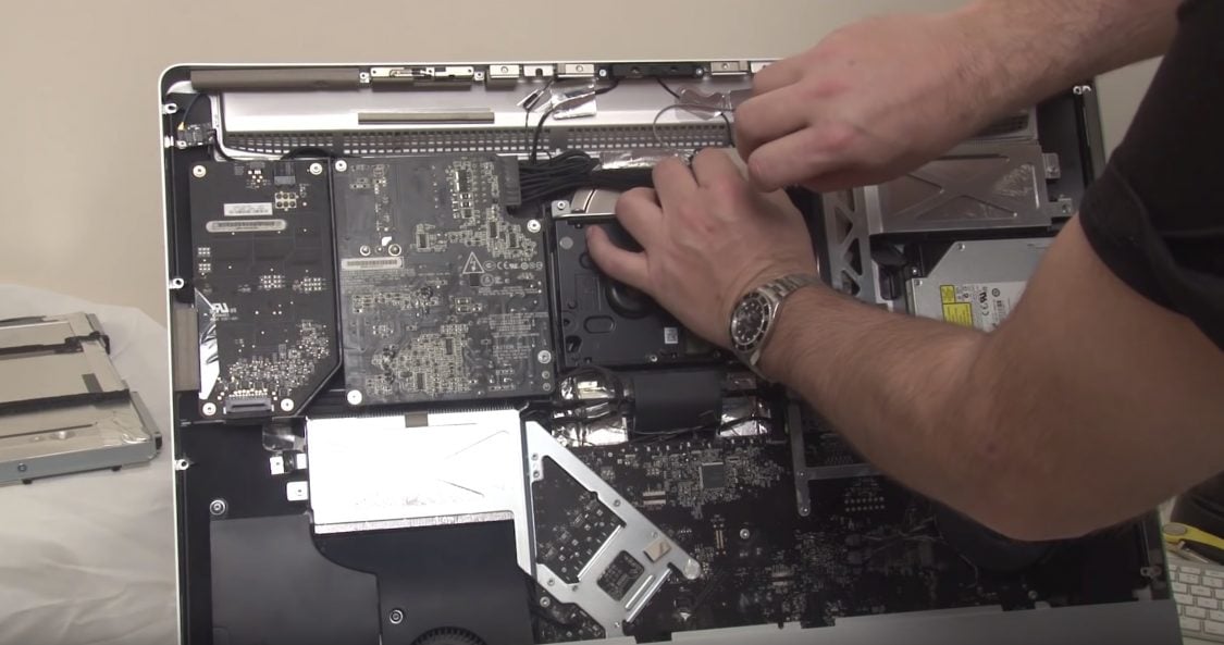
Remove the optical drive, screen backlight supply and main power supply boards, and then the main board – see video
Install the new SATA cable for the SSD drive – either use the third SATA port or remove optical drive SATA cable and use that port – depends on your iMac model
Replace the main board and PSU baords, take a lot of care routing the new and existing cables, there is very little room for error here
Install the SSD drive using double-sided sticky pads – make sure its well fixed, you do not want it coming loose as it will interfere withe air flow that cools the GPU – this will Kill your iMac!!
Re-install the optical drive (with or without being connected), the drive carrier acts as part of the air ducting…
Install the new 2TB drive
Fashion a suitable temperature sensor for the new HDD, I simply used a 2N2907 transistor which works a treat from what I can tell
Re-assemble the computer
Power up and make sure it boots to the new SSD drive
Log into the “admin” account you created – this should be the only account on the system
If all has gone well you should have a fresh new OS and you should be logged in as administrator. The next thing we need to do is re-create the accounts and then re-locate their home directory.
Follow these next steps carefully…
First of all you need to create a new account for each account you have re-located. In my case the account I relocated is “gerrysweeney”. So go into the System Preferences/Users & Groups tool, unlock it if needed, then create the new account. By default, this will create a new account home folder on the SSD, thats OK, we will need to deal with that next. If you have more than one account you have re-located, create a new corresponding account for each one. When you create the account, use the same password as your previous account, this way your keychain will remain accessible and valid once you re-instate your home folder.
Now you have a new account with a new home folder on the SSD drive, the next thing is to modify that account and point it to the home folder you previously re-located. In my case the account was “gerrysweeney”. In the Users and Groups tool, press the “Ctrl” key and click on the account name, you should get a menu option called “Advanced Options…”, select this. The “Home Directory” field will be set to “/Users/gerrysweeney”, you should change this to “/Volumes/Users/gerrysweeney”. Again, do this for each account you have re-located.
UPDATE: Having done this I realised that later on I still have to set up a symbolic link to the home folder which is a couple of steps below. In lights of that you can simply skip the above step of modifying the account properties to re-locate the home directory. Once the symbolic link is in place it will work without doing this.
Now we need to change the permissions of each account’s home folder data to the account – this is important to re-syncronise all permissions. Open a terminal window and for each account you have re-located you should issue the following command: –
This command will change the ownership of every file in this folder, including the folder its self and all sub-folders and files. Now I am not sure this is exactly right, it is feasible there are system files that should be protected from the user but I don’t know – what I done worked OK so its pretty safe. In any case you need to do this for every account you have moved – remember to replace “gerrysweeney” with the right account name.
Now you have given the right ownership to your files, we now have to deal with the fact that much of your existing configuration will be looking for profile and other content from /Users/gerrysweeney, and the way we deal with that is by creating a symbolic link. In the terminal window you should issue the following command to delete the newly created home folder on the SSD drive that we no longer need.
sudo rm -rf /Users/gerrysweeney
Now you should create a symbolic link to map the expected home folder location to the relocated folder on the new 2TB drive. To do this you should issue the following command:
You should do this for each account you have relocated. You can double check this operation worked by issuing the following command:
ls -li /Users
which should show you something like this...
total 8
 135869 drwxrwxrwt  13 root   wheel  442 13 Oct 20:22 Shared
 329606 drwxr-xr-x+ 13 admin  staff  442 14 Oct 10:18 admin
1056113 lrwxr-xr-x   1 root   admin   27 14 Oct 10:17 gerrysweeney -> /Volumes/Users/gerrysweeney
You can see that gerrysweeney is pointing to /Volumes/Users/gerrysweeney
The next thing we need to do is recover your applications. You have the option of simply re-installing them all but thats a right royal pain, I found this worked really well and mostly re-instated everything for me.
Get your original 1TB disk and using the Disk Copy Station connect to the computer via USB, you should be able to see this drive in finder. Make a note of the volume name for the drive – in my case this was “Macintosh HD”. In order to recover the applications, you basically need to copy all of your Library and Application Files to the SSD. To do this issue the following commands: –
Now with all that done, you should eject the original 1TB HDD using Finder and you should shutdown and re-start the computer. While re-booting you can unplug the Disk Copy Station, you should not need it any more.
At this point you should be able to log in using your original account – in my case this was “gerrysweeney”. If everything worked out OK then you will now have a working system, your desktop, applications and settings should all be restored and in the same state as they were before you started.
Set aside a day to do this, its a pain, there is a lot of fiddling around and there is a lot of waiting for stuff to copy. In the end though its a worthwhile mod that Apple does not want you to do.
Enable TRIM
UPDATE: I had found this after I finished the article and Anton pointed out in the comments I should include this information because it is important. Thank you Anton.
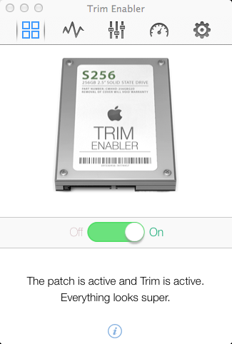
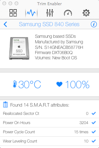
In order to maintain the healthy state of your SSD and prolong its life you need to enable the S.M.A.R.T features and make the OS and the SSD Drive communicate using the TRIM commands. This basically allows the OS and the SSD drive to play nice and help prolong the life of the SSD by minimising erase cycles, the OS simply informs the drives that blocks are no longer in use. Doing this is easy, you can simply install a piece of software called Trim Enabler which takes care of this for you. If you want to know more about TRIM you can read this wikipedia article
IMPORTANT DISCLAIMER
DO THIS AT YOUR OWN RISK. I HAVE PROVIDED THIS ARTICLE IN THE HOPE THAT IT WILL BE USEFUL FOR OTHERS. HOWEVER, YOU SHOULD KNOW THAT OPENING YOUR COMPUTER INVALIDATES ANY WARRANTY YOU MAY HAVE AND WHILE THIS APPROACHED WORKED FOR ME, IT MIGHT NOT WORK FOR YOU AND IF IT ALL GOES WRONG FOR YOU I CAN NOT BE HELD RESPONSIBLE. THERE ARE LOTS OF DELICATE AND SENSITIVE ELECTRONICS THAT ARE EASILY DAMAGED IF YOU DO NOT HAVE EXPERIENCE HANDLING THEM – PLEASE ONLY DO THIS IF YOU ARE CONFIDENT IN YOUR OWN ABILITIES
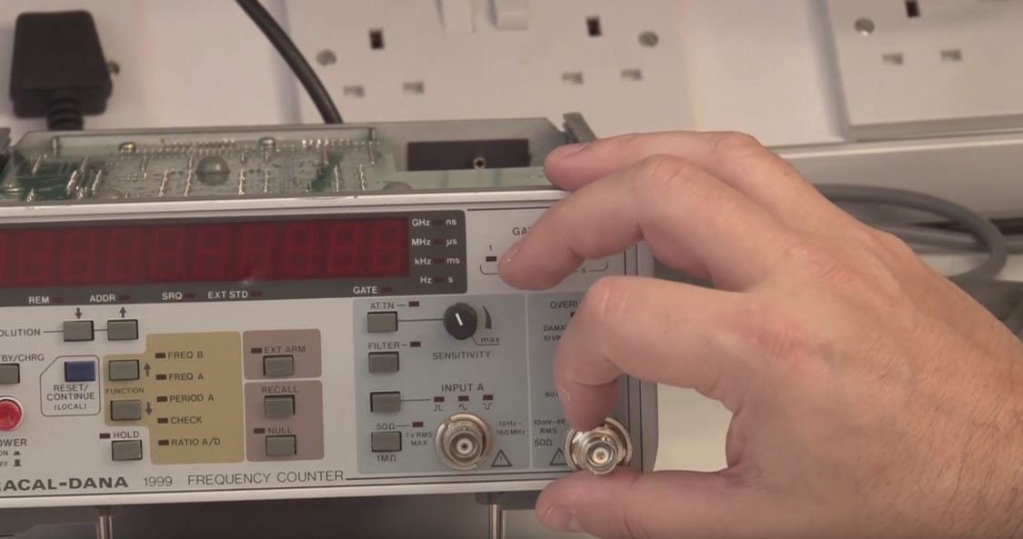
Having played with a number of OCXO’s and a Rubidium standard I tried (after repairing it) to calibrate the standard timebase in my Racal-Dana 1999 counter which is actually a simple TCXO. I could get pretty close but it was touchy and not easy to be totally precise. In response to that vlog article a number of people suggested it would be nice to do an OCXO modification to the Racal counter so I decided to do exactly that, and I done it on a budget too…
One of the problems with this counter is the lack of any 12v supply that is able to provide enough current to drive the OCXO’s oven, so I had a look around and found an OCXO made by Isotemp model OCXO131-100 that runs on 5V which is perfect for this build because the counter has a good 5v supply that can easily drive the additional current required – I have provided a download link for the data sheet for the OCXO I used below below. I ordered one from a seller on e-bay and used that as the basis for the hack.
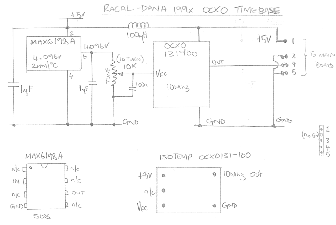
The other key component needed to implement a stable OCXO board for this counter is a “temperature stable” variable voltage between about 1 and 4 volts, this is used to fine tune the OCXO to allow the oscillator to be calibrated. To get me a suitable reference voltage I have used a MAX6198A, chosen simply because I had some to hand – but also because they have pretty darn good temperature stability too.
Schematic
Here is the schematic I used to create the OCXO board.
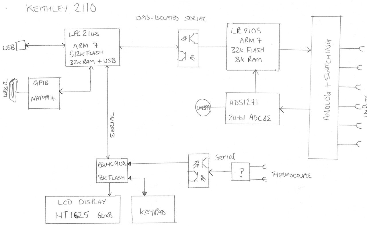
Following on from my review of the Keithley 2110, I tamper with the tamper-proof seal and open up the meter to see what was inside. While I am there I have a look at the build quality and the overall system architecture. Keithley have a long history of building quality test equipment and I thought it would be nice to see how the latest kit from Keithley stacks up to their past reputation.
The meter is easy to get apart and is built really well, nice solid construction and really very difficult to fault – apart from the really poor LCD display. Please see the video for the details as they unfold.