I said last time I would look at the software and firmware for this post but I decided I needed to spend more time on the regulator to address the DC response issues I had observed, I felt this was more important to get right so this article focuses on that. The good news is, I have achieved good results and I believe the regulator design is complete – at least for the high current version of the module (0-8V 0-8A).
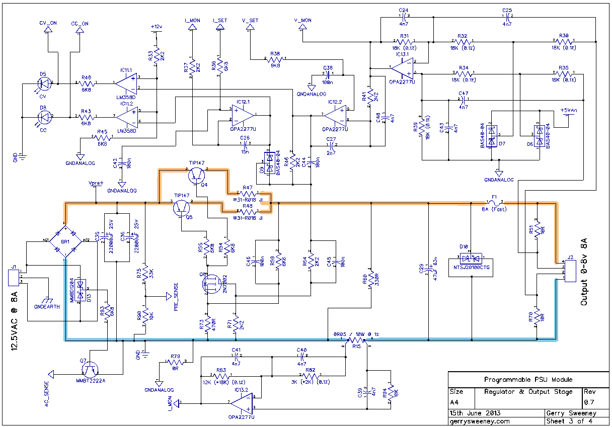
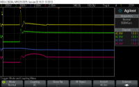
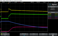
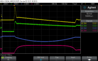
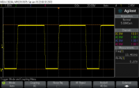
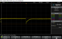
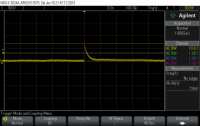
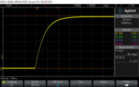
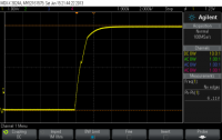
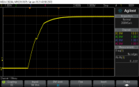
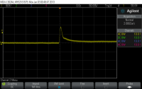
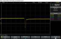
I had problems with the regulator over shooting by about 500mV when transitioning from a high power load to a low power load. There were two main problems, the first was down to the inductance of the wiring on the output, that creates a problem which in turn was amplified by the relatively slow response of the various amplifier stages. I have achieved significant improvement on my previous measurements by tuning response times through the various stages, this simply required lowing the impedance through the various stages to ensure the servo was able to respond more quickly to changes on the output. This was achieved by adding C24, C25, C39, C40, C41, C43, C45, C46, C47 and C48 to the input and driver stages. I also needed to throttle back the fast rise time of the control drive from the DAC to follow behind the response curve of the regulator circuit. These changes mean the regulator now delivers a clean and very acceptable dynamic response to fast-switching load conditions.
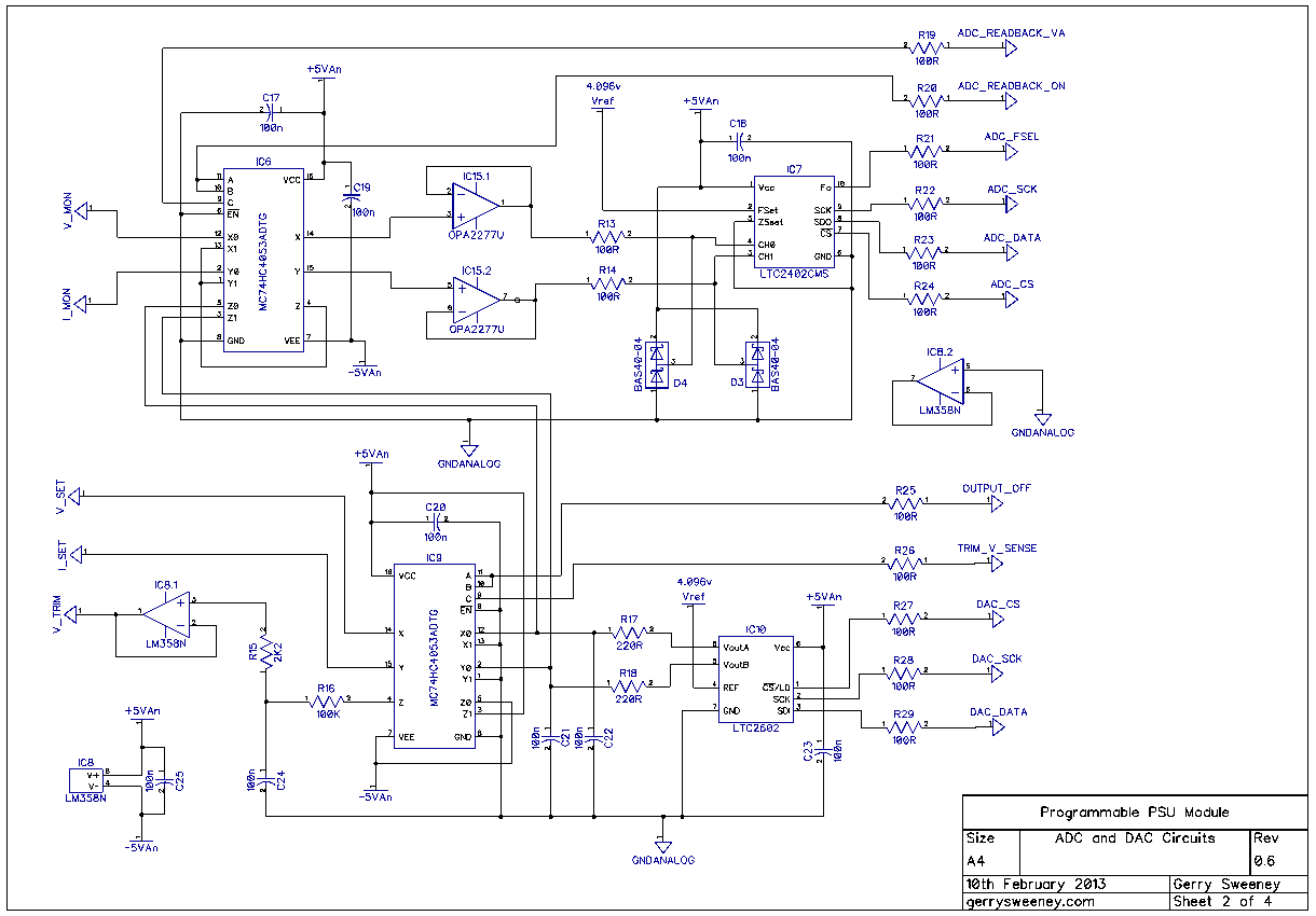
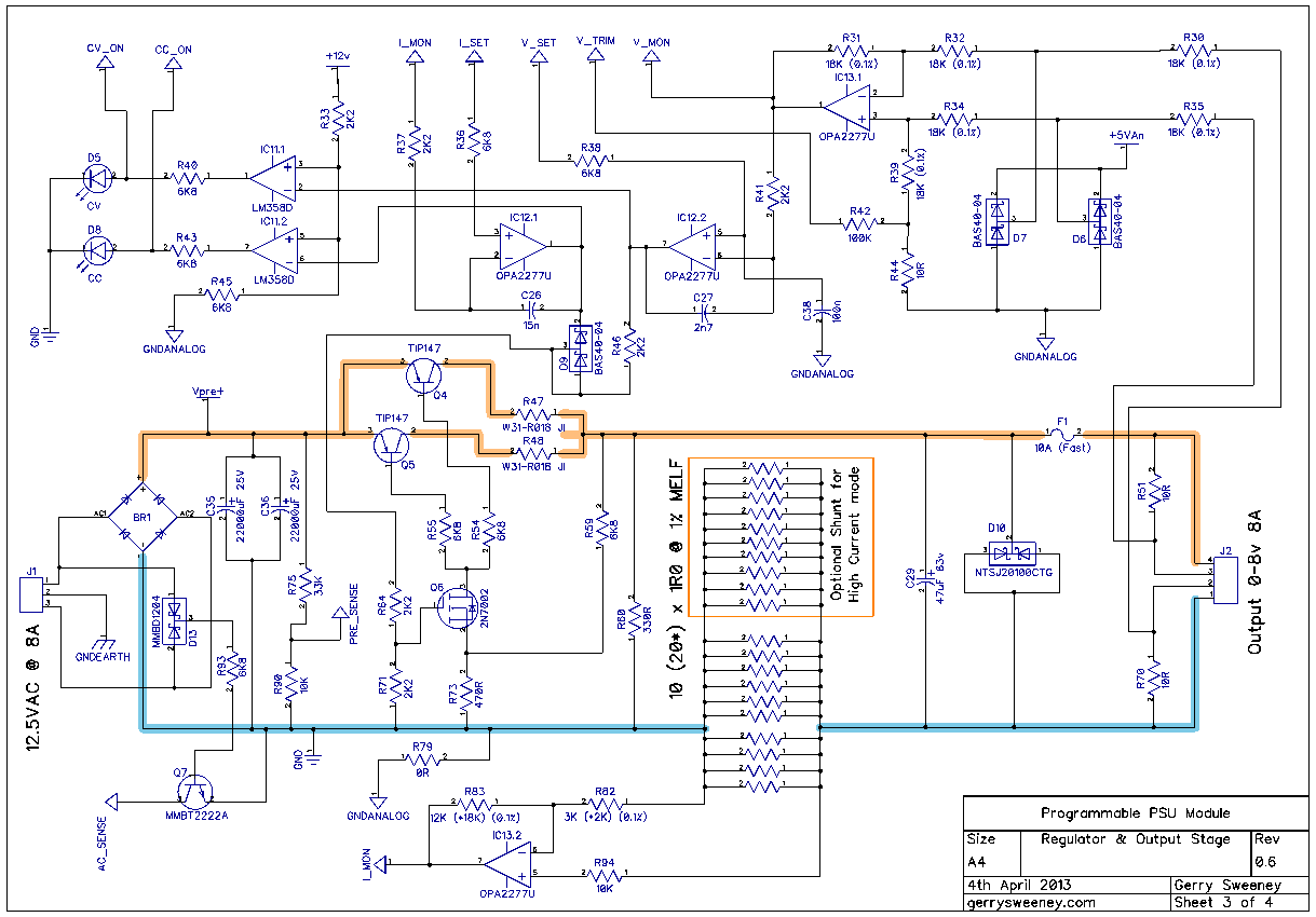
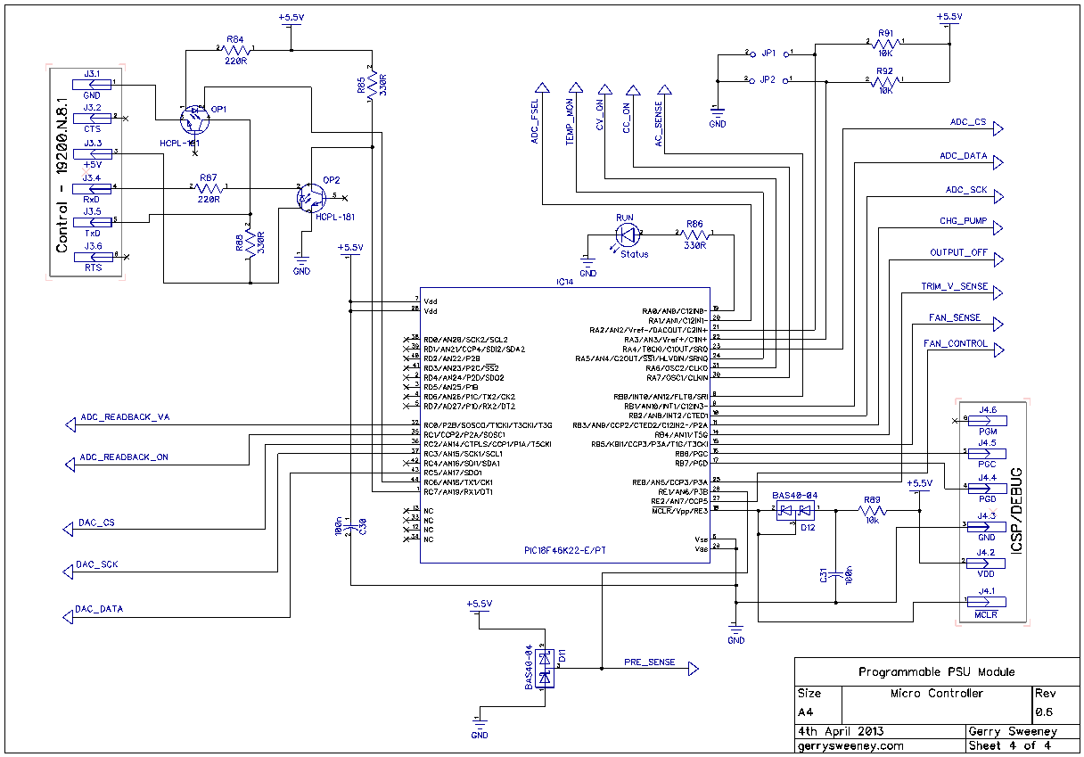
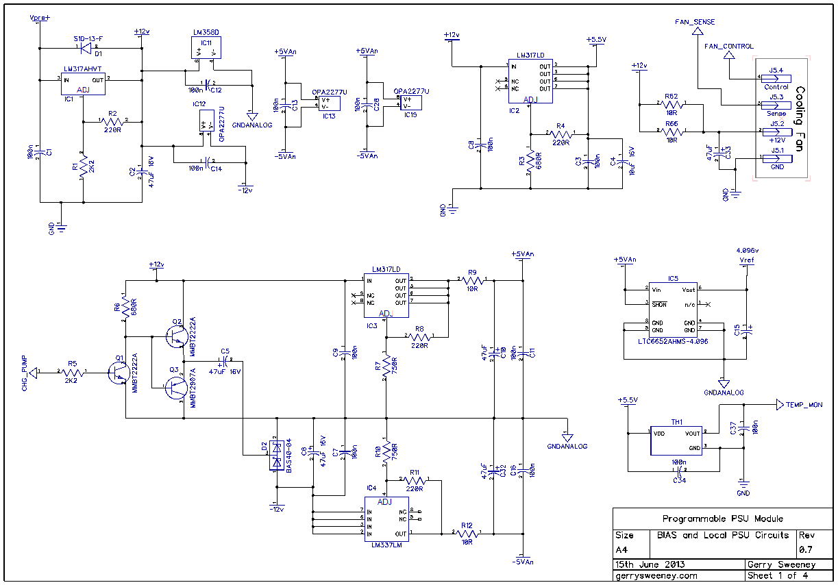
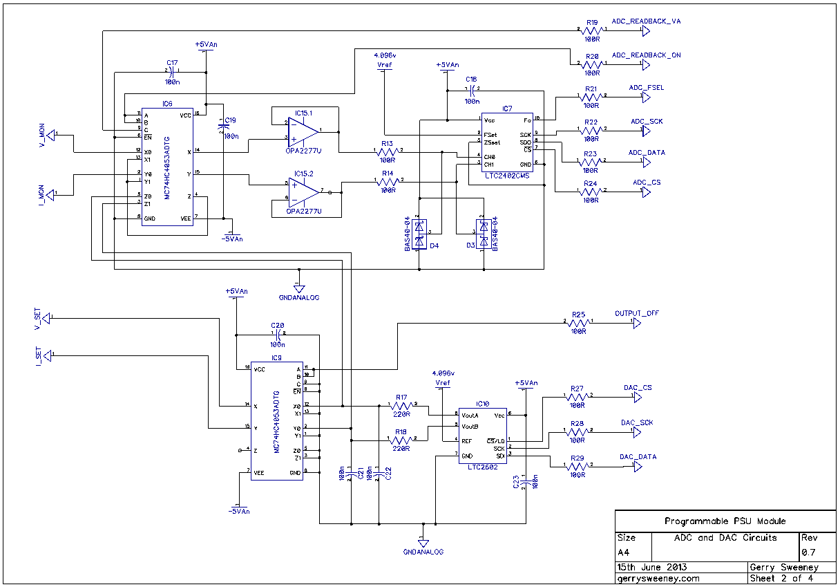
The Schematic
Here is the latest schematic which is at version 0.7 including all of the latest changes. The most significant changes are on sheet 3.
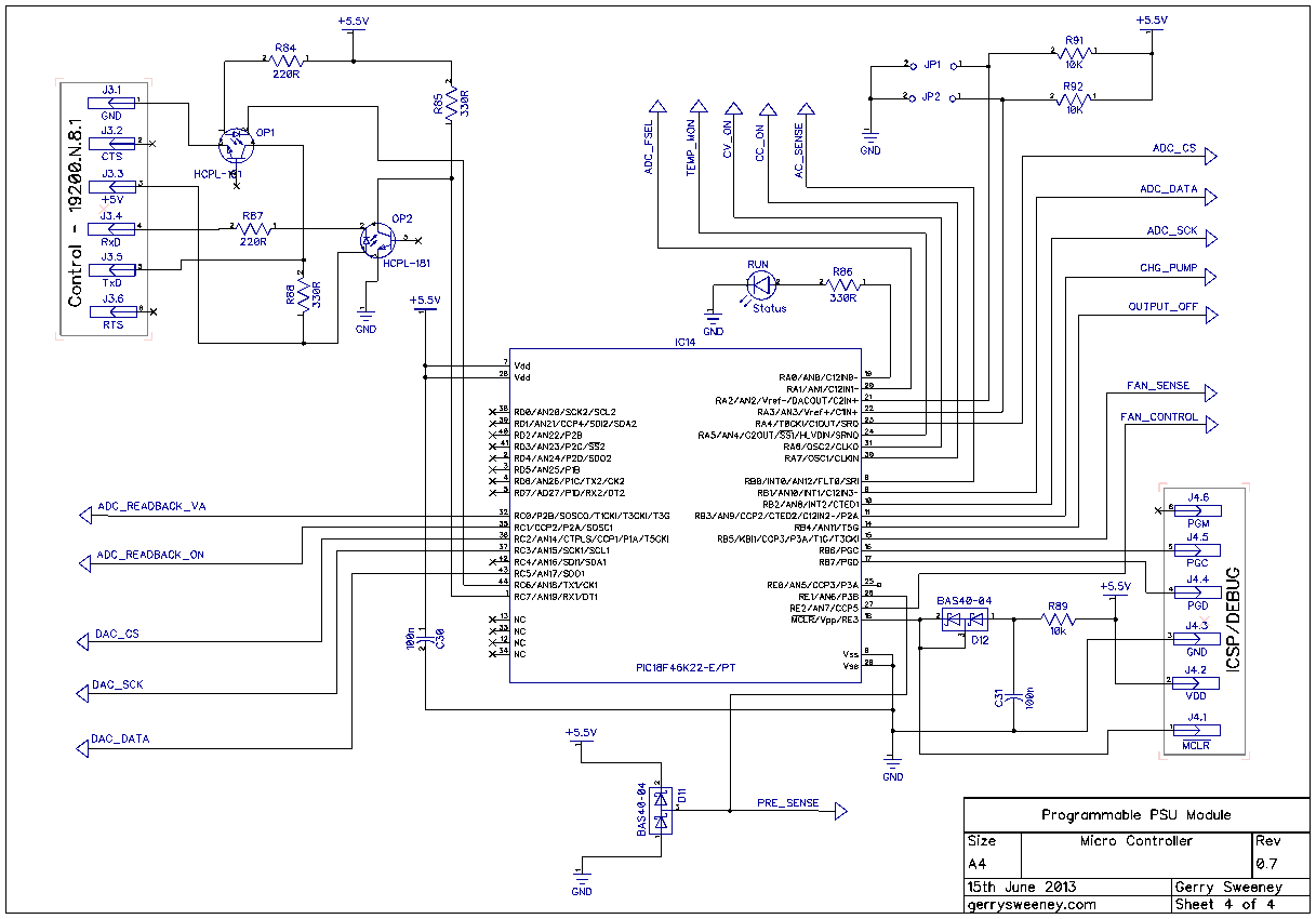
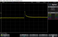
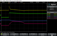
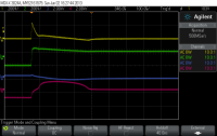
Various Scope Traces from Testing

I now need to lay out the new PCB and get some ordered, I will do this over the next couple of weeks. I will definitely cover the development environment and the firmware in the next post as well as the serial protocol used to control and monitor the module.
Thanks for watching.