I have been working on various power supply projects of late and was finding that my approach to loading PSU with simple incandescent laps was limiting. What I needed was a programmable DC load so I wondered – build or buy? Because I am already working on a PSU I decided that its probably better to buy one if I can find something that was reasonable quality and at a reasonable price. So I searched around and eventually took a chance on a Maynuo M9711 DC Electronic Load. I had not heard of the company before and could not find much out about them on on the internet, what I did see what that other similar devices that cost twice as much and had a reputable brand (BK Precision for example) were so similar in form that I thought its a good chance that they are different OEM’s of the same design. I am not sure that is the case because I do not have a BK Precision to compare, but I bought the M9711 brand new from the manufacturer on the basis that this was likely the case. Was I disappointed with the purchase? we shall see…
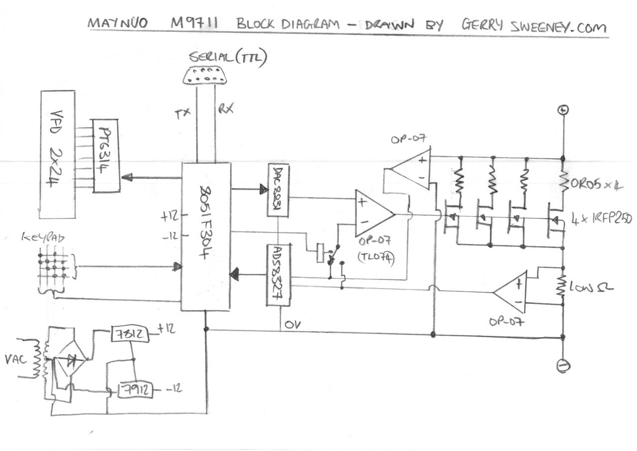
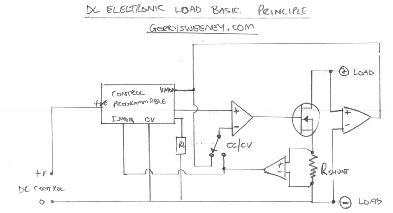
In this video I unbox and then tear down the Maynuo M9711 DC Electronic Load so we can take a look inside and see how it works and how well its been built. I try to explain how a DC electronic load works and I present a block diagram of the Maynuo M9711 based on my understanding and the cornerstone components that I find.
The main funcional components found in the device are:
The power MOSFET (x4 in 150W model) used as the main active power device that creates the load load
Notes and Diagrams
Below are the diagrams I present in the video describing the operation of a DC Load and the basic high-level layout of the M9711. You can browse these images or download a PDF document to print out if you prefer.
Well I hope you find this useful, thank you for reading and watching, catch you next time…
So I present the third in what is starting to feel like a long line of Agilent PSU repairs, but before you read on you should know that I have now depleted my collection of broken Agilent E36xx series power supplies so I will need to find another subject to blog about next time! That being said, even though I have blogged about two other PSU;s from the same family, I thought it would be worth videoing the repair exercise and at the same time try to demonstrate how I go about identifying and resolving a fault on this kind of circuit. The E3646A is a different model to the other two PSU’s I have repaired and blogged about – this one is a dual output 0-8v @ 5A / 0-20V @ 2.5A for each channel and the internals are different so I hope this will be of some use for anyone who may need to repair one of these.
I hope you find this useful or interesting. If you do please give the video a thumbs up and if you have any comments or suggestions please post them here and I will do my best to answer them.
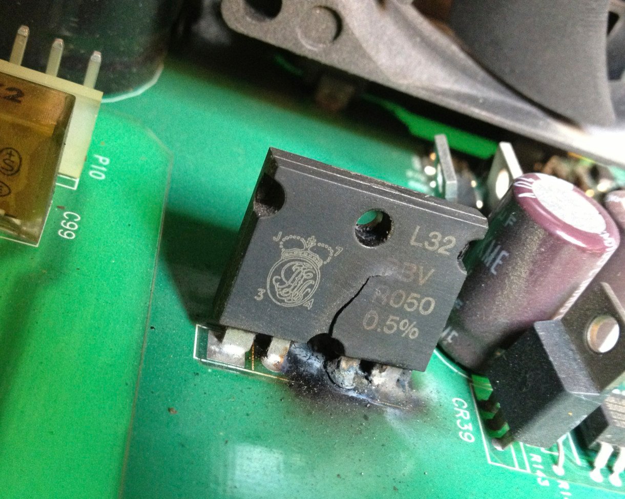
Over a year ago now I repaired a HP/Agilent E3631A triple output PSU and have been using it very often ever since. Recently I bought an Agilent E3634A PSU which is a single output but high power supply, I bought it in non-working condition for not very much money (about $90). It turned out to be a non-trivial task, with physically burned out components and a difficult to track down and understand secondary problem. The components to repair the supply cost less that $20 and the repair exercise was challenging and educational so well worth the effort.
SMOKIN’ HOT…..
I decided that for this repair I would try doing a video teardown and repair which I have not done before. The repair took quite a few hours in the end, although I carried out the repair over about 4 weeks elapsed.
This is a really useful addition to my work bench, the high power nature of this supply makes it very useful for working in low voltage systems like audio amplifiers communications equipment and automotive applications that have high power requirements.
The Agilent E3634A Service Manual with schematics is available on the internet for download, I have provided a link here for convenience.
It took a while to decide on the final form factor, I wanted to consider cost and ease of mechanical construction before committing to a layout for the PCB. My original design goal was to make a completely self-contained module for a single fully isolated channel of programmable DC power and my thinking was extending to thermal management. My original idea was to rely on the module to be thermally fixed to a heat sink which could be decided upon by the builder. However, heat sinks are expensive usually and construction would depend on what heat sinks you may have to hand so I thought it would be nice to make this more flexible and use components that are easy to find and obtain for very little money. As a general rule, if you can buy something off the shelf this is always going to be cheaper than making your own, and if you can use off the shelf components that are mass-produced then all the better. I got to thinking about the heat sink I needed – force air cooled and able to handle 100 watts of dissipation in a small space that is mass produced, with a built in fan that can be controlled for quiet and efficient operation, is commonly and easily available, is of standard physical construction, good quality and cheap to buy – enter the common PC CPU Cooler, which meets all of those criteria.
So thats what I have done, I have built the PSU module into a form factor that easily accommodates the CPU cooler and still remains 100% self-contained. The built module with all required power components, mechanical construction with heat sink and cooling fan measures only 150mm wide by 80mm deep by 90mm tall. All you need to make it work is a mains transformer, four 4mm banana output jacks and something to control it via a serial interface.
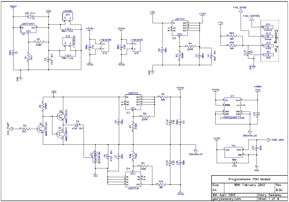
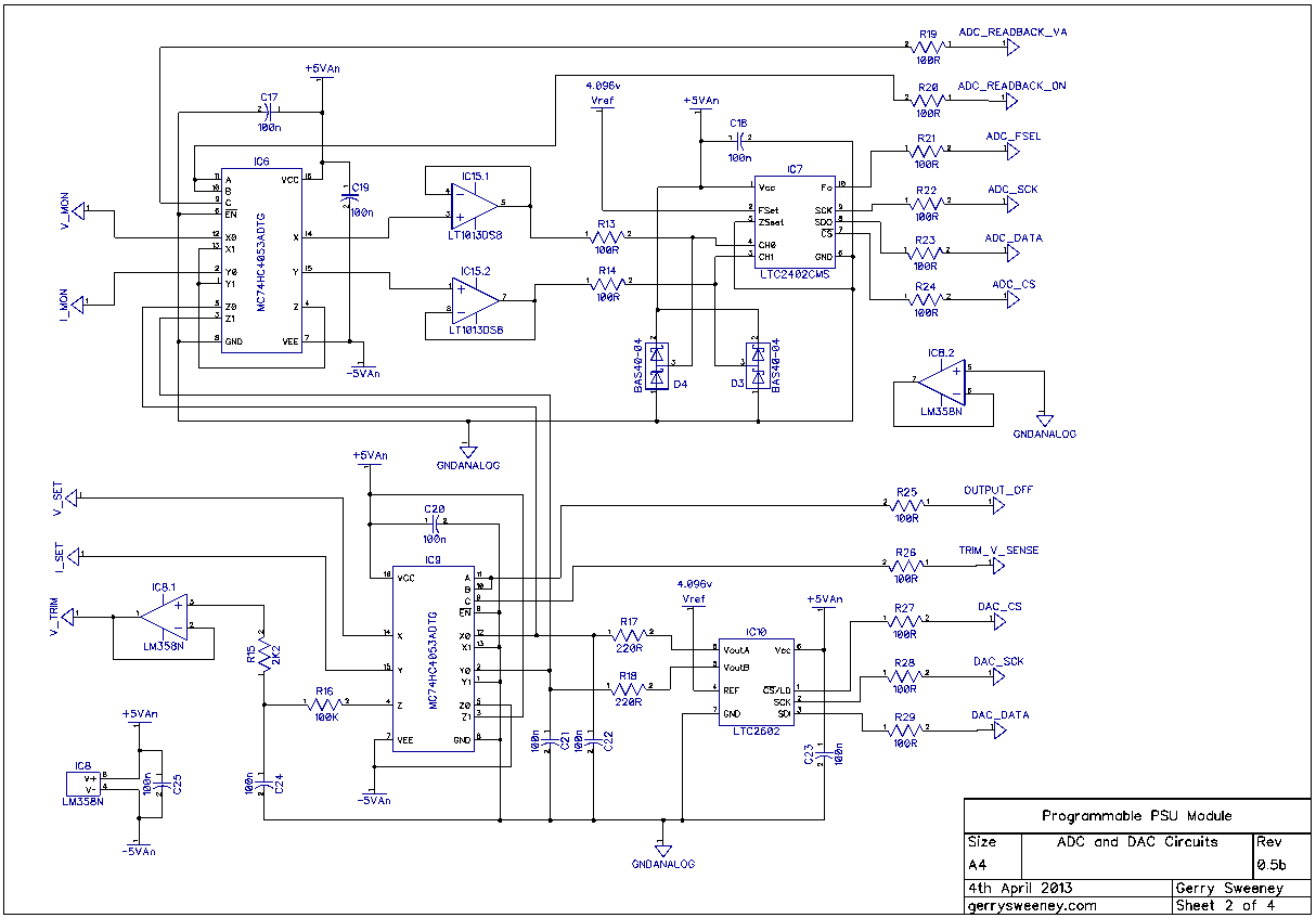
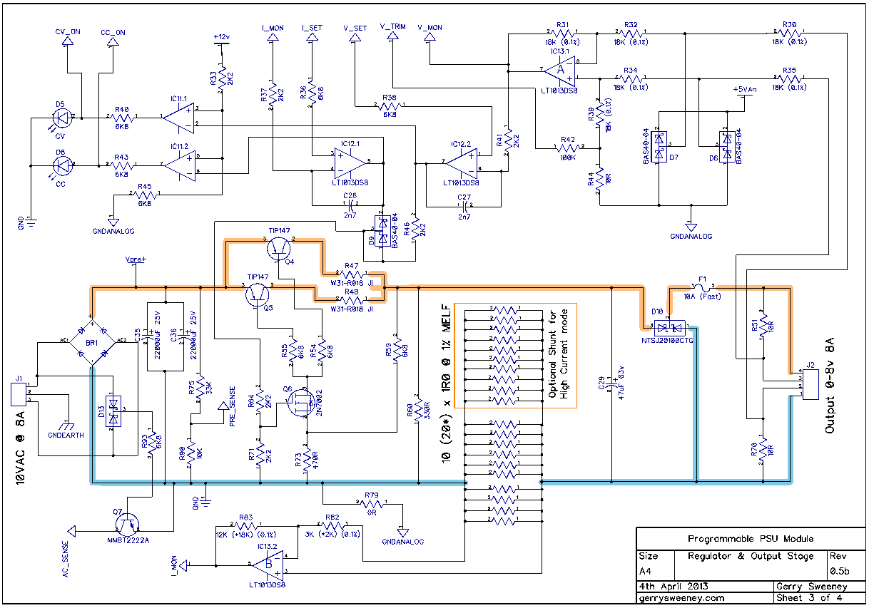
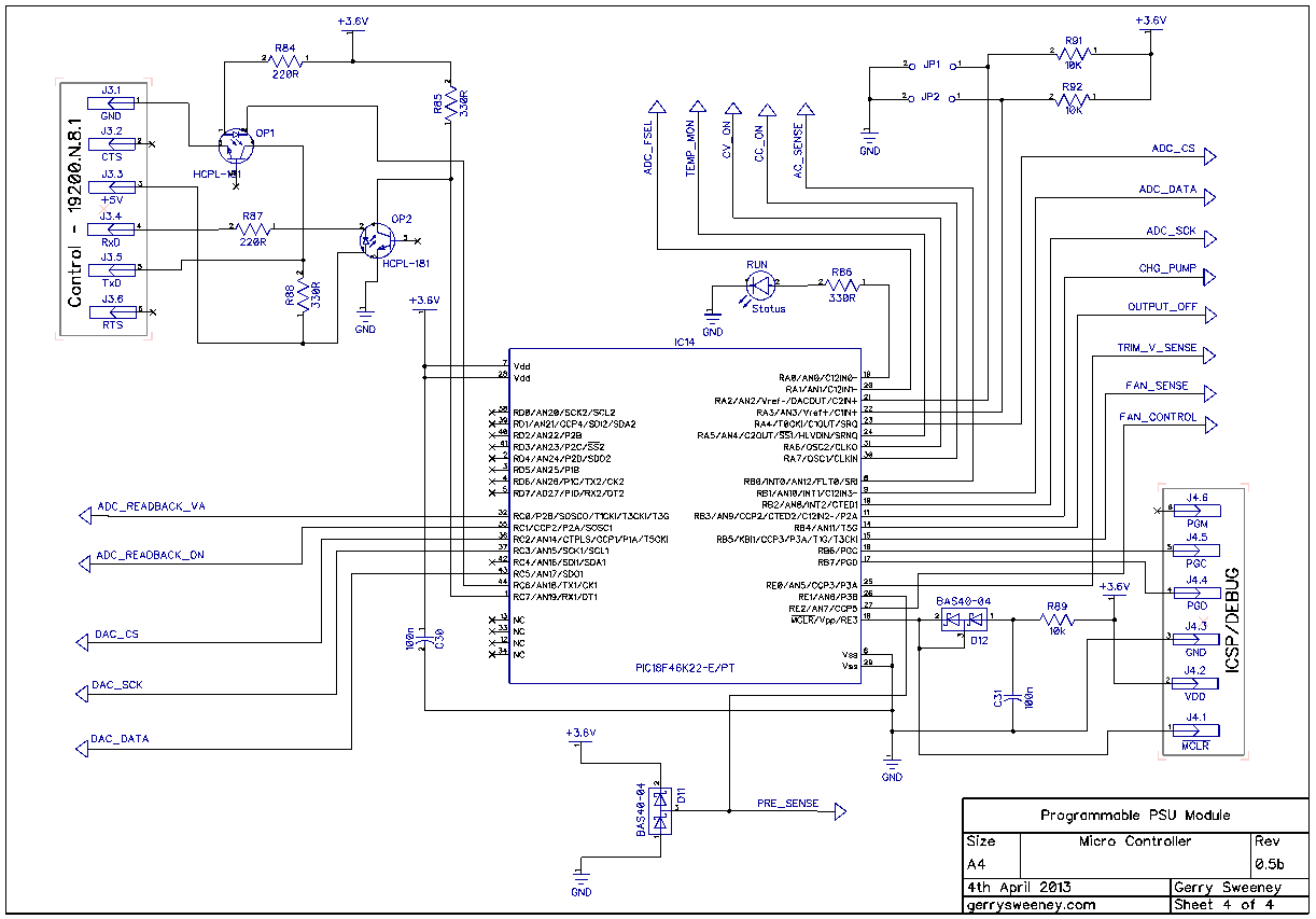
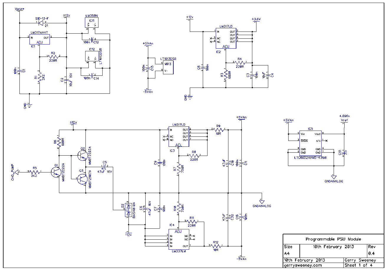
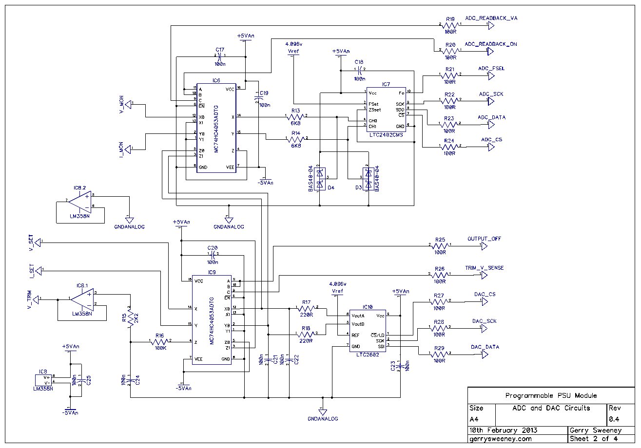
The Schematic
I have updated the article to include the schematics which I had previously omitted.
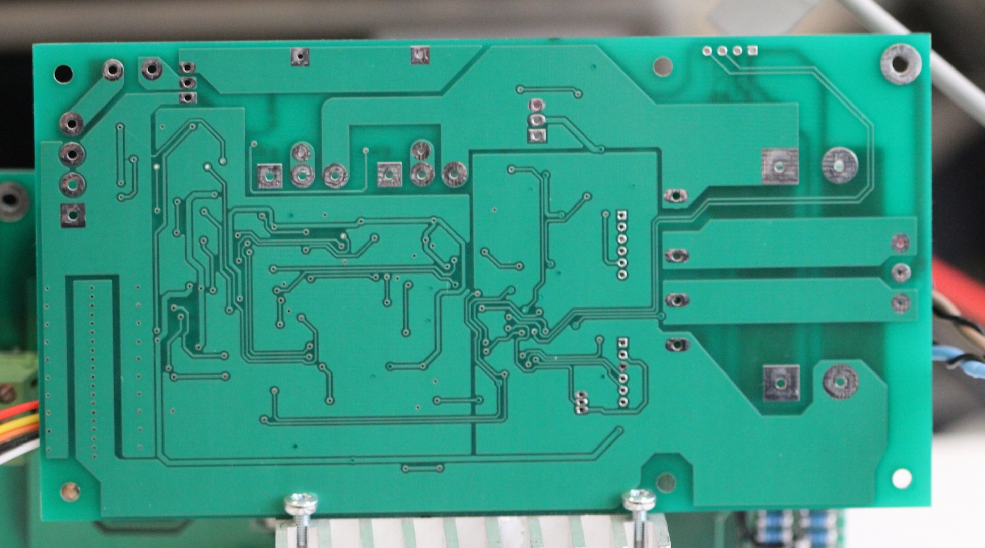
The PCB
The PCB is made with 2oz Copper to handle current and provide better thermal mass. The high power path is run 5mm thick tracks (minimum) and run on both sides of the board. Where possible the top and bottom tracks are joined at the through-hole pads for the power components which is everywhere except at the current shunt resistor. For this I have many small via’s connecting the top and bottom traces to handle current and thermal bonding.
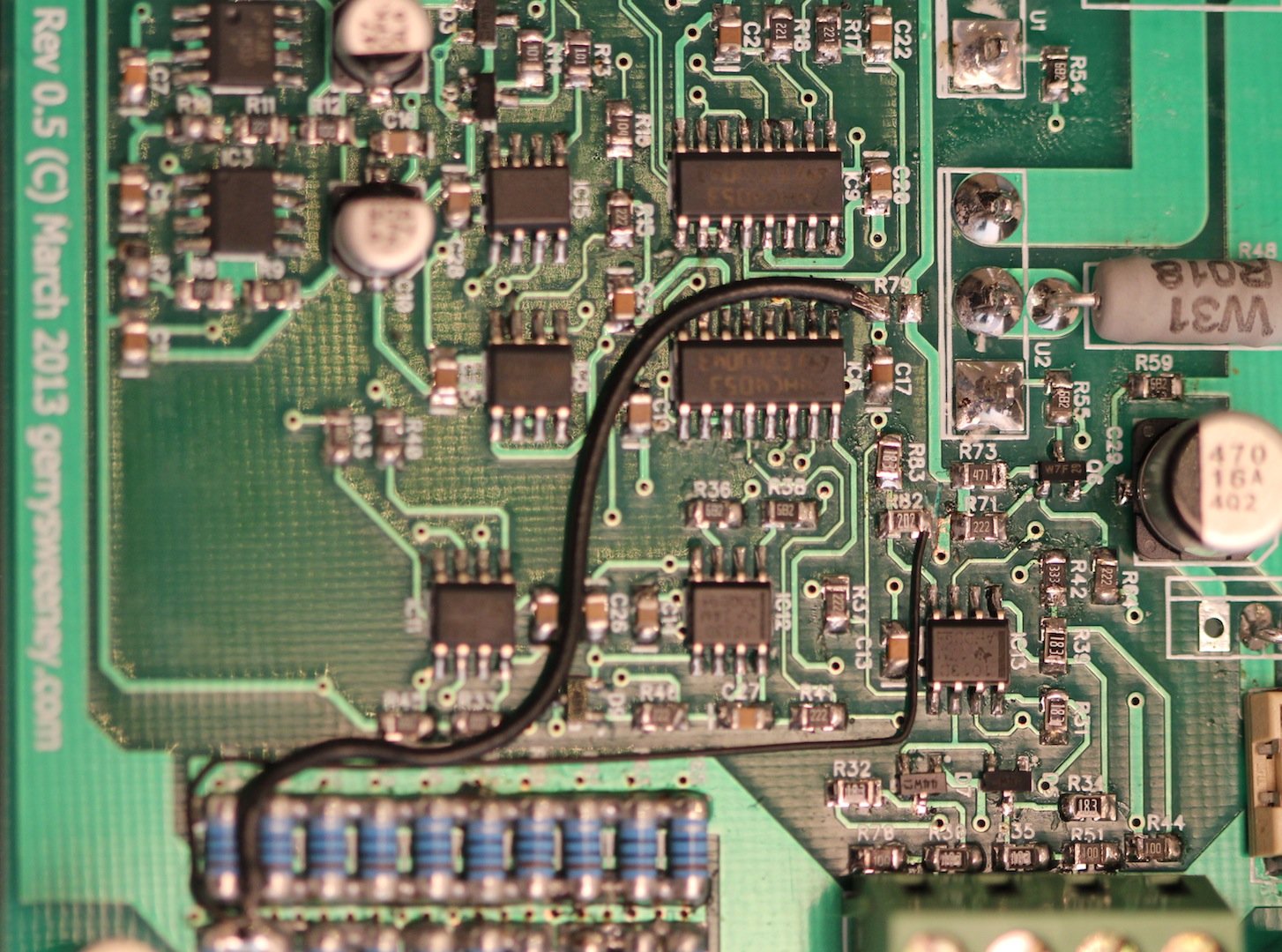
The BODGE WIRES
In laying out the PCB I forgot to pay attention to the star earthing I had set out in the previous post. The impedance of the ground path makes a big difference when you are looking at the lower 1mV of the range. Using DipTrace I had to use a ZERO ohm resistor to properly segregate GND and GNDANALOG nets, but I physically routed to the GND side of that resistor to the wrong point. I done a pretty similar thing on the low-side current sense connection. As a result there are two bodge wires on the board (see photo below). The first is the GNDANALOG to GND connection – Instead of installing R79 (which is ZERO ohm) I have taken a wire from the bottom pad down to the low-side of the current sense resistor array. The second is slightly more difficult to do, I had to cut the track from the top pad of R82 and then again take a wire down to the low-side of the current shunt resistor.
Thermal Management
In order to manage the thermal properties of the module, the firmware simply uses the temperature measurement of the heat sink to set the fan speed calculated on the following basis: –
below 25 degrees centigrade – FAN is idle at its lowest speed (0% PWM)
25 to 50 degrees centigrade – FAN is driven with variable PWM 25 degrees = 1%, 50 degrees = 100%, which is a rate of 4% per degree of temperature rise
more than 50 degrees centigrade – FAN is driven at 100%
Controlling a 4-wire fan is pretty easy, the specification developed by Intel describes the electrical interface and requirements for both fan control as well as fan manufacturers. I have added the Intel 4-Wire PWM Controlled Fan Spec as a download on this page for convenience. The fan I tested and used in the video above runs at about 1500 RPM to 3400 RPM with a 0-100% duty cycle on the PWM control signal. The taco output is open collector and provides 2 pulses per revolution.
Next time I am going to *try to* characterize the PSU. I don’t have much experience doing this which is why I say I am going to *try* – none the less I should be able to pull together some basic specs and test conditions.
Following that, I am going to design and make a front panel controller for the PSU. Although I am making this specifically for this project I am thinking about making this more generic so it can be used in other systems and/or test equipment. The basic goal is to create a single PCB front panel with a 4×20 VFD display, some buttons and controls, a micro controller (PIC32 or maybe ARM) with RS232, USB, Ethernet (and possibly a GPIB interface module) with 3-4 independent TTL level internal serial interface channels (to connect to PSU modules for example). Don’t know, all just thoughts at the moment, we shall see…
Whenever I am faced with watching a video with poor sound quality I feel compelled to stop watching. Its strange that with a media as visual as video how important the sound aspect is. Poor sound makes watching a video really hard, try watching a film on TV where the sound is so low or muffled that you can’t hear the dialect properly – it does not matter how good the film is, without decent, clear sound you will just not enjoy it. As I started to make some video content for my blog I was getting frustrated with the quality of sound I was able to produce. Mostly I am in a room where there are a lot of hard surfaces so the audio ends up full of sound reflections, sounding hollow when using the camera’s built in microphone. There are a number of factors that drive sound quality, including dynamic range and frequency response and the ability to reject unwanted noise. Probably the biggest contributor to poor quality sound though are the reflections you get when you are recording in an enclosed space. To understand what this is, imagine getting one of those small bouncy rubber balls and throwing it hard at a wall, the path the ball will take will be unpredictable and the ball will bounce around the room uncontrollably – this is what happens with sound. The microphone not only picks up your voice, but also picks up some of the reflections which are slightly delayed, and the recoding ends up sounding hollow – like when you sing in the bathroom – sounds OK in the bathroom but this effect really sucks on video.
A good way to solve this is to get the microphone close to you, this way your voice is at a much higher level than the reflections in the room and you get better quality sound. However, being close to a microphone is not always practical or desirable. I want to get good quality sound for my video content but I don’t want to have to be near a microphone, or wear a head set and I also want to be able to move around freey – so no wires either. Getting good sound quality requires you to understand where the poor sound comes from, it takes some practice and most importantly some decent gear too.
I have put together a video comparing various microphone options using my Canon Legria HFS-21 camera and the following microphone combinations: –
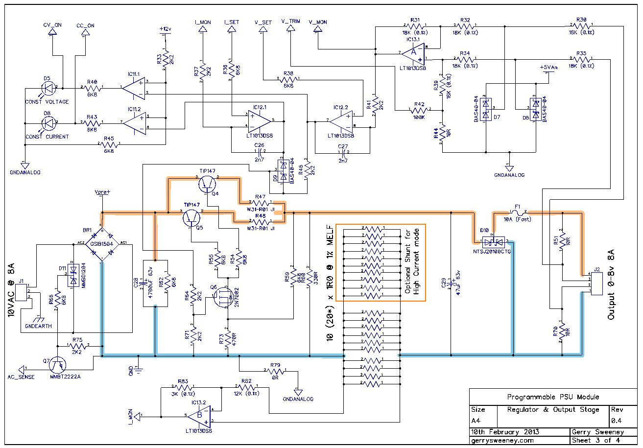
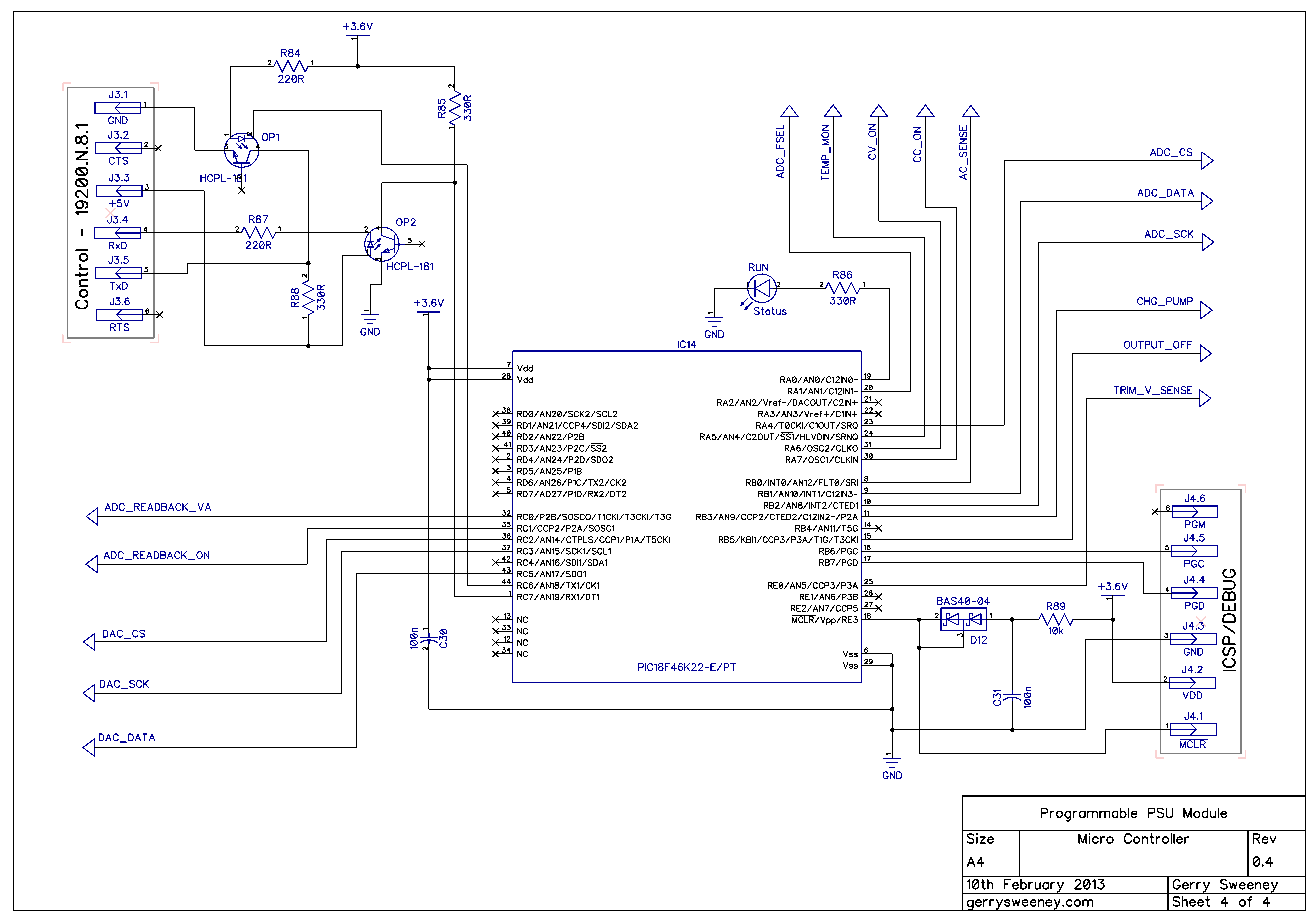
Here is the latest Revison 0.4 schematic which represents the power supply design as described in this blog and videos with the latest round of prototyping and testing.
The headline changes from last time are as follows: –
I have added -Ve supply using a simple charge pump and a PWM drive from the micro controller.
I have added a difference amplifier to correctly handle remote voltage sensing for both PSU voltage control and output voltage read back
I have modified the design to use low-side current sensing instead of high-side current sensing. In doing so I have dropped the use of the high side current sense amp MAX4080 and made use of a spare op amp element instead. This saves a $3 part and replaces it with half of a $2 part
Removed dedicated buffer amp previously added to drive the ADC, the new design removes the need for this because the voltage and current monitoring are better buffered now. This saves another $2 part.
Moved to a faster micro controller PIC18F46K22 which has more memory, more PWM outputs and more I/O pins. No real reason apart from I needed a second PWM output. The firmware is pretty much compatible.
Here is a video overview of the design changes and latest prototype hardware and test setup as well as some basic tests showing load regulation and programmable voltage accuracy benchmarked against a calibrated HP 34401A bench meter.
NOTE: I used a different mic setup and the sound is really poppy and crappy! My apologies…..My dustbin now has a new microphone in it!
So I am working on the final PCB now, in Part 12 I should have a finished module….whoop whoop….Please do comment and like the videos if you find them interesting. Thank you for watching.