As part of the process of upgrading my counter to have a DIY high stability OCXO (Oven Controlled Crystal Oscillator), someone who watched my videos had designed a DIY 3GHz Channel 3 53131A-030 option board. The original from Agilent is very expensive (obviously) and there are clones you can get on e-bay which are a quarter of the price Agilent charge which is why he decided to design his own. His name is Andy and when he saw my video’s he got in touch and offered me one of the PCB’s to which I of course said YES PLEASE 🙂
Now as it turned out, when Andy constructed his own board he had enough components left over so also constructed and tested one for me which was a really kind thing to do and very unexpected too. In exchange for this I have insisted that I can build him an OCXO board while I am doing mine to return the favour.
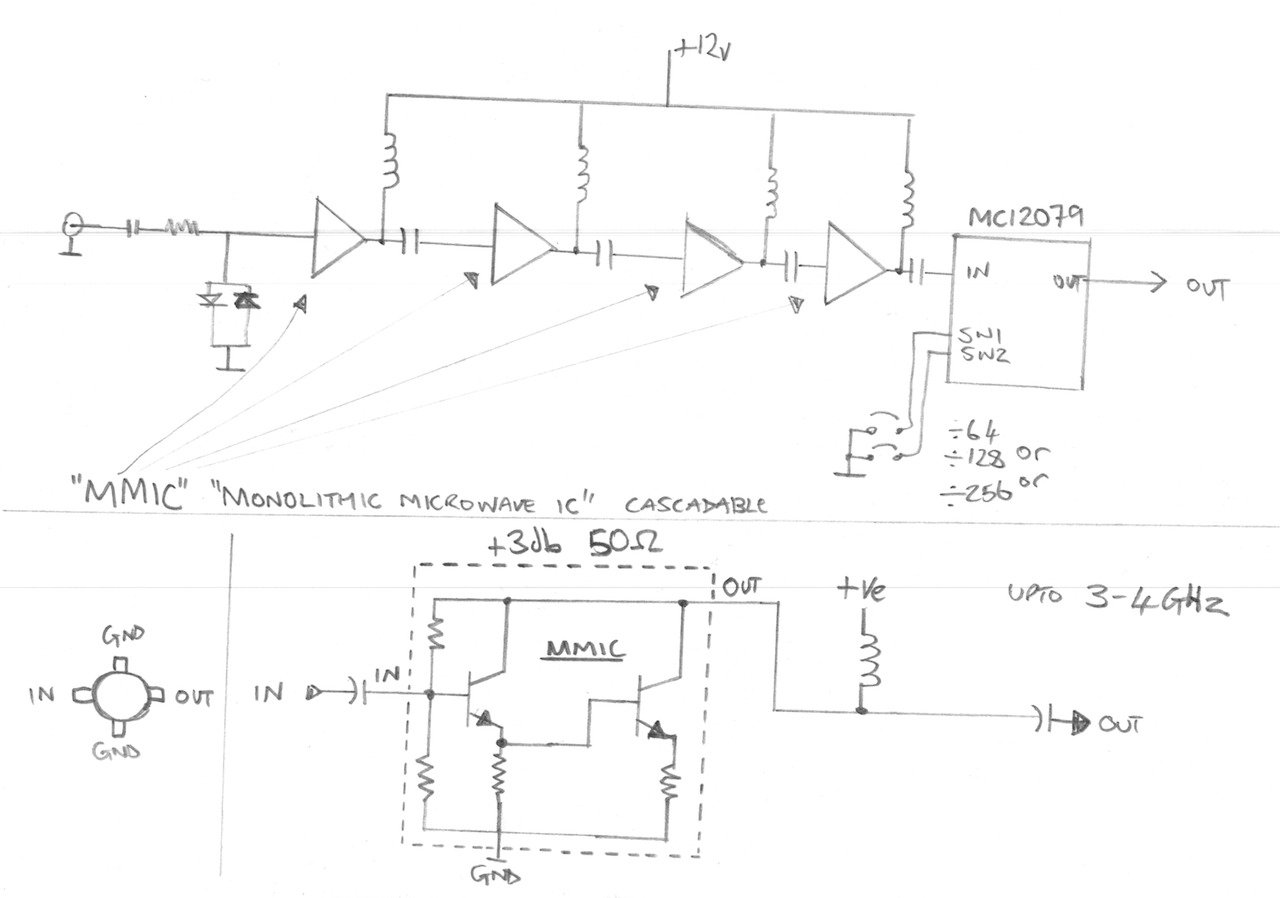
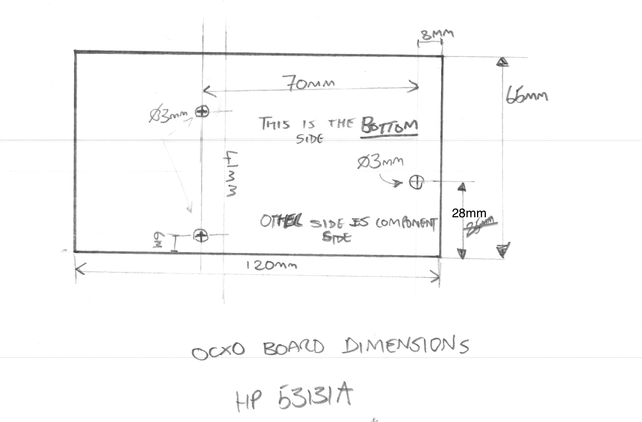
Anyways, I thought I would do a video to show the HP/Agilent 53131A-030 DIY 3GHz Cannel 3 Option board getting fitted to my counter. I also spend some time explaining how the pre-scaller circuit works and in basic terms what MMIC’s are and how they work too. I also make an adaption to my previous hard power switch modification to make way for the upcoming DIY OCXO board, and I measure up to get the exact board dimensions and mounting hole positions I need for the OCXO PCB layout.
The entire work and full attribution for the DIY 030 option board/PCB goes to Andy, so Andy – thank you so much for making one of these for me – I really appreciate it.
PLEASE NOTE: I will not put Andy’s Youtube/EEVblog ID here unless he asks me to, and I will not pass on his details without his express permission so please don’t ask – I respect people’s privacy. If Andy does want to share his details in connection with this project then I will gladly put them here.
PLEASE ALSO NOTE: The schematic drawing below is technically incomplete and is meant as an illustrative block diagram. In the real circuit there is also a resistor in series with each inductor at the top of each MMIC to set up the right DC conditions.
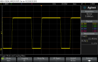
I have had my HP 339A for a long time now and despite only using it a small handful of times it is a really great instrument – but – its big and takes up a lot of shelf space. A few weeks back a purchased a Keithley 2015 THD which is a 6.5 digit bench meter with a built in distortion analyzer, I bought it because of the distortion analyzer function. I would like to get some more instrument shelf space back so am able to replace the HP 339 with this 2015THD I will make that much-needed space. I decided to build a simple output circuit so that I can induce some crossover distortion and compare the basic measurements on these two devices to see the results. Now I must make it clear that this is a basic 101 on measuring distortion, I am sure there is a lot more to know that I do but I believe I cover off the basis.
The simple drawing I used to explain the test and test circuit.
I will tear down the HP 339A on video to show how nicely these are built. This is one of those rare “all analog” devices that has not digital parts at all, watch out for that video if you like seeing the guts of nicely built equipment.
I have spent a lot of time over the years prototyping electronic circuits and the amount of resistors that have ended up in the trash because they are so cheap you don’t bother to keep them tidy or organised once you take them out of their organised storage – you know the story. One potential solution to this is a programmable resistance box but the problem with these things are they are bulky and expensive and do not lend themselves well to breadboard prototyping. The cost of construction means they are typically the reserve of high-precision resistance boxes. I have a CROPICO RBB6E resistance box in my lab which I open up to have a look inside, its really well made, mostly by hand too, far too nice to abuse in prototyping….
I looked around at what is available but did not find a solution that met my own requirements so I decided to design something simple myself. I also wanted to make a simple project to get manufactured by machine which apart from other things requires reasonable volume, and I thought this project would be useful enough to others that I should get some made and make them available.
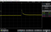
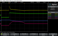
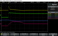
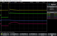
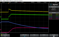
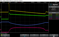
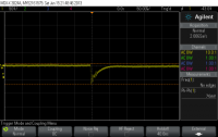
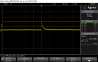
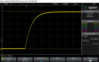
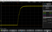
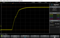
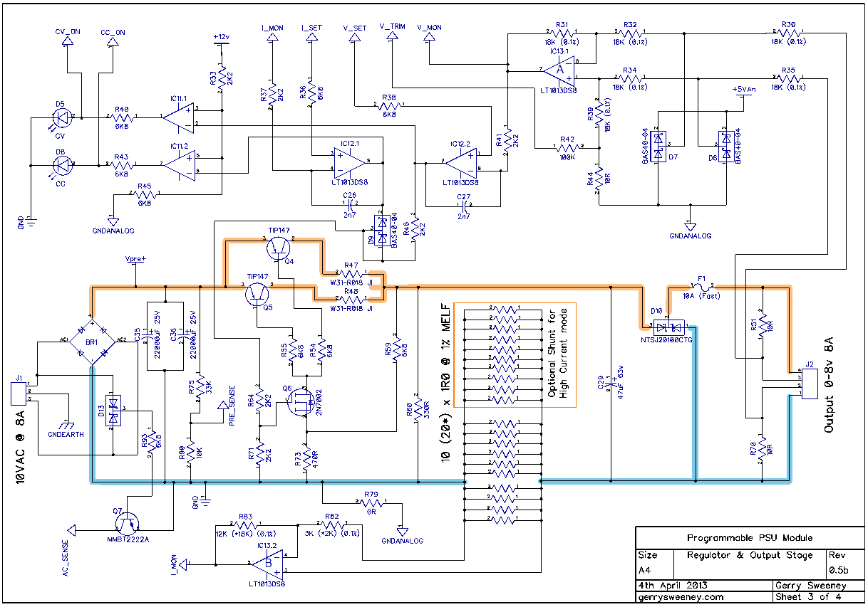
I said last time I would look at the software and firmware for this post but I decided I needed to spend more time on the regulator to address the DC response issues I had observed, I felt this was more important to get right so this article focuses on that. The good news is, I have achieved good results and I believe the regulator design is complete – at least for the high current version of the module (0-8V 0-8A).
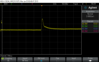
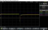
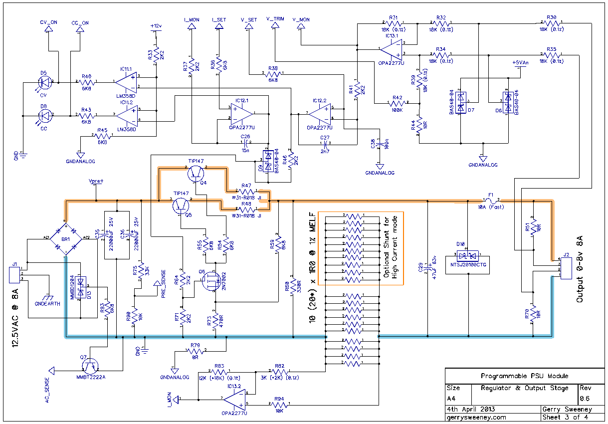
I had problems with the regulator over shooting by about 500mV when transitioning from a high power load to a low power load. There were two main problems, the first was down to the inductance of the wiring on the output, that creates a problem which in turn was amplified by the relatively slow response of the various amplifier stages. I have achieved significant improvement on my previous measurements by tuning response times through the various stages, this simply required lowing the impedance through the various stages to ensure the servo was able to respond more quickly to changes on the output. This was achieved by adding C24, C25, C39, C40, C41, C43, C45, C46, C47 and C48 to the input and driver stages. I also needed to throttle back the fast rise time of the control drive from the DAC to follow behind the response curve of the regulator circuit. These changes mean the regulator now delivers a clean and very acceptable dynamic response to fast-switching load conditions.
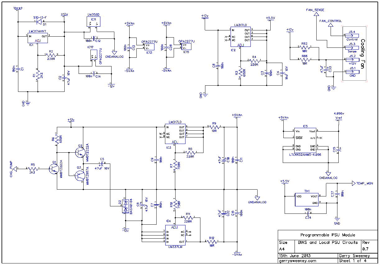
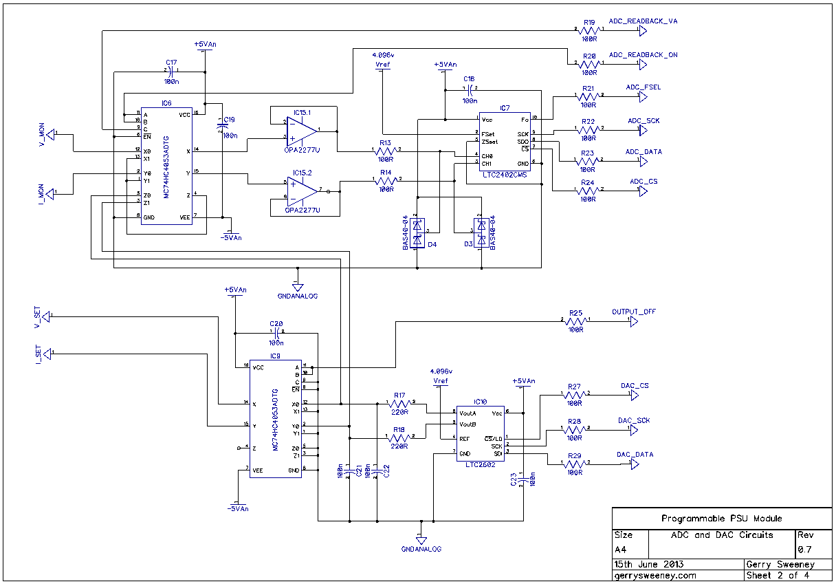
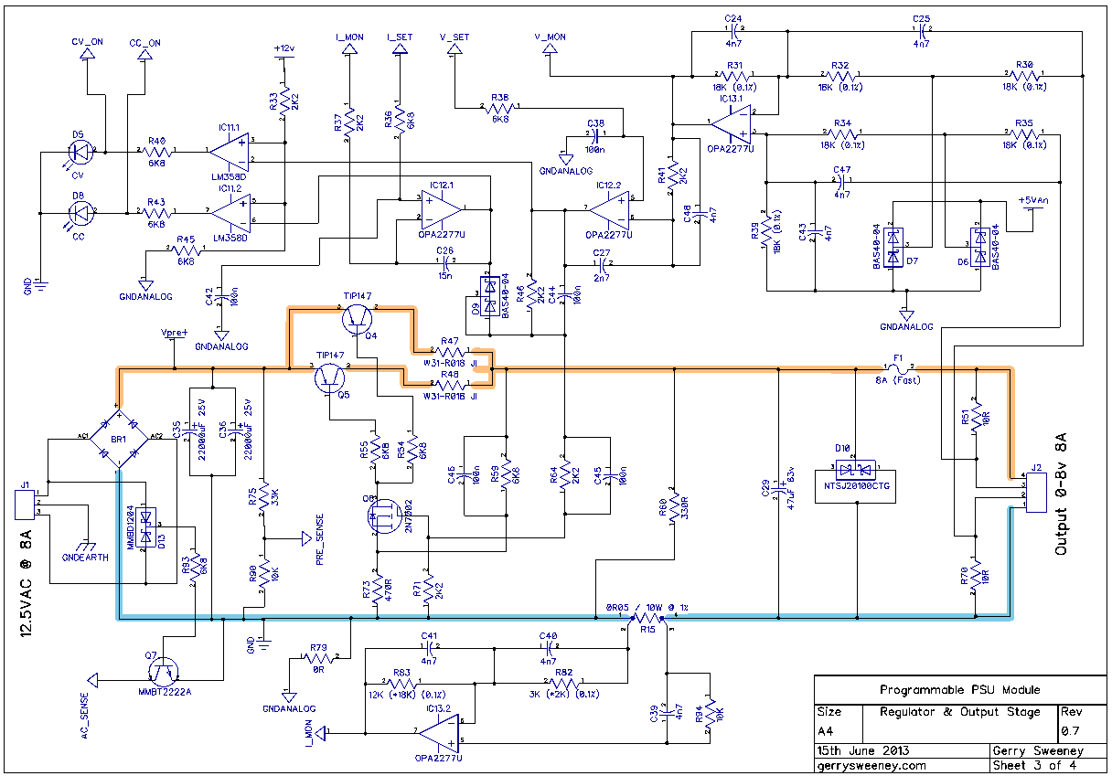
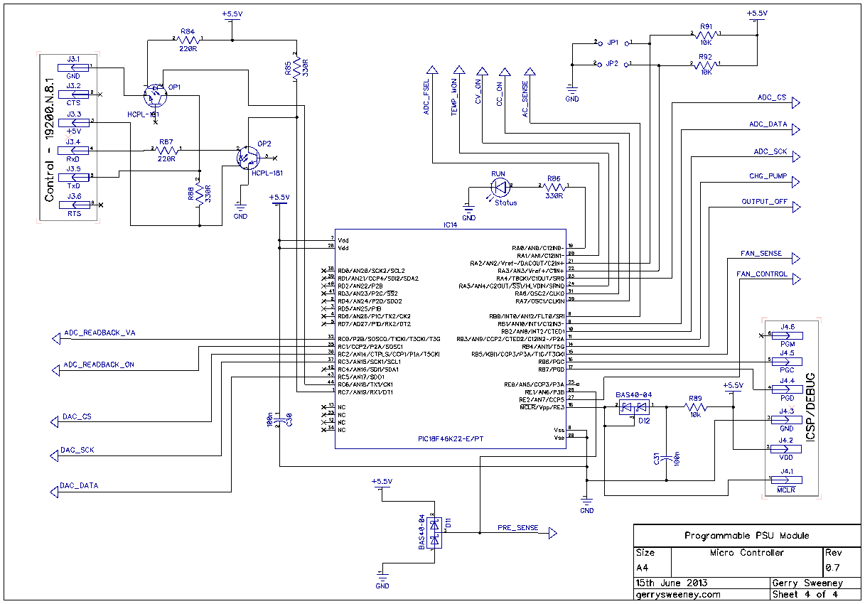
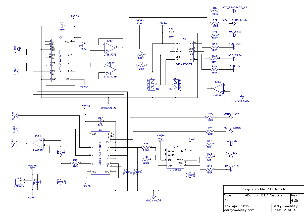
The Schematic
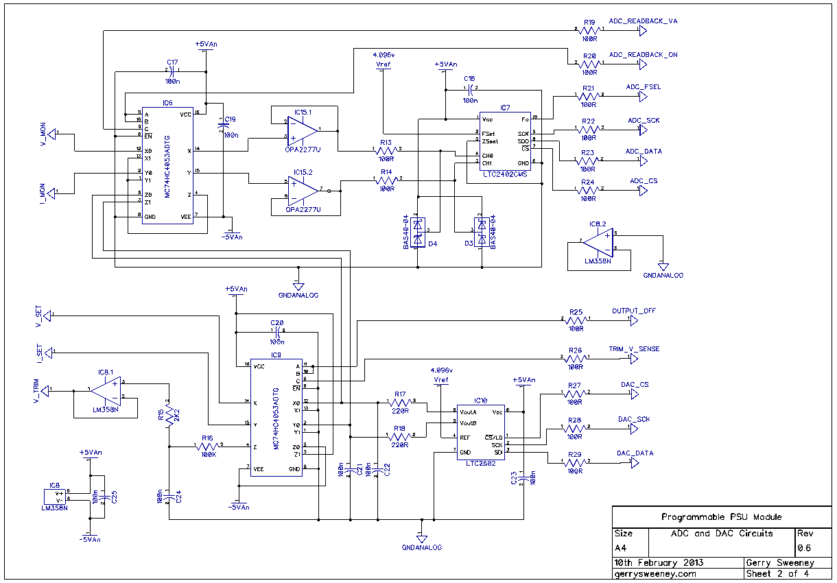
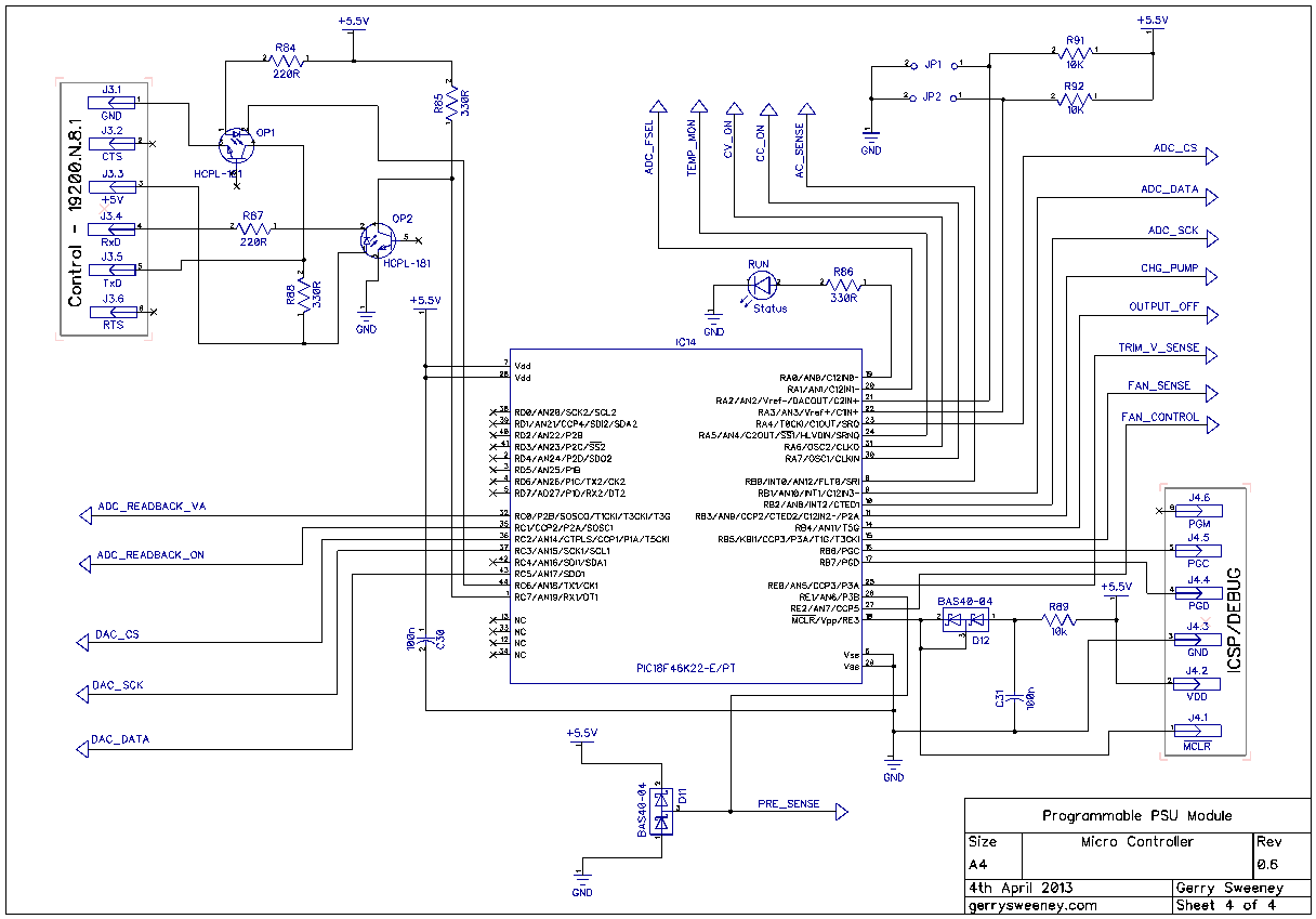
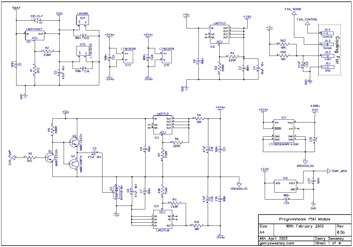
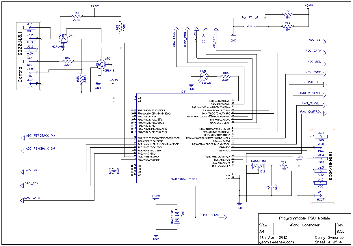
Here is the latest schematic which is at version 0.7 including all of the latest changes. The most significant changes are on sheet 3.
I now need to lay out the new PCB and get some ordered, I will do this over the next couple of weeks. I will definitely cover the development environment and the firmware in the next post as well as the serial protocol used to control and monitor the module.
It’s taken me a while since the last update, I have been real busy of late. Having completed the first physical build, I now need to make various changes to the construction. Given the screw-up of the star earthing topology on the first board, I need to layout another board revision so I am going to make a bunch of other improvements. In this article I cover the various design changes and perform some basic power, DC condition and regulator response tests, I identify and resolve some issues and re-select better performing op-amps as an alternative to the LT1013, I have selected the OPA2277U part, and I have also tweaked the power supply implementation for the drive circuitry to reflect the fact that the newly specified op-amp is not a single-supply rated part.
The Schematic
Here are the latest schematic which is at version 0.6 including all of the latest changes.
I now need to test and resolve (or decide its acceptable) the overshoot problem when testing the load/no load dynamic response of regulator. I also need to re-layout the next board revision, get some boards made and build the next version. In Part 14 I am going to cover the firmware, describe the development environment and show the basic software layout as well as details on the current serial protocol I am using to control the module.
Thank you for your continued interest in this project, please give the video a thumbs up if you have found it interesting.
It took a while to decide on the final form factor, I wanted to consider cost and ease of mechanical construction before committing to a layout for the PCB. My original design goal was to make a completely self-contained module for a single fully isolated channel of programmable DC power and my thinking was extending to thermal management. My original idea was to rely on the module to be thermally fixed to a heat sink which could be decided upon by the builder. However, heat sinks are expensive usually and construction would depend on what heat sinks you may have to hand so I thought it would be nice to make this more flexible and use components that are easy to find and obtain for very little money. As a general rule, if you can buy something off the shelf this is always going to be cheaper than making your own, and if you can use off the shelf components that are mass-produced then all the better. I got to thinking about the heat sink I needed – force air cooled and able to handle 100 watts of dissipation in a small space that is mass produced, with a built in fan that can be controlled for quiet and efficient operation, is commonly and easily available, is of standard physical construction, good quality and cheap to buy – enter the common PC CPU Cooler, which meets all of those criteria.
So thats what I have done, I have built the PSU module into a form factor that easily accommodates the CPU cooler and still remains 100% self-contained. The built module with all required power components, mechanical construction with heat sink and cooling fan measures only 150mm wide by 80mm deep by 90mm tall. All you need to make it work is a mains transformer, four 4mm banana output jacks and something to control it via a serial interface.
The Schematic
I have updated the article to include the schematics which I had previously omitted.
The PCB
The PCB is made with 2oz Copper to handle current and provide better thermal mass. The high power path is run 5mm thick tracks (minimum) and run on both sides of the board. Where possible the top and bottom tracks are joined at the through-hole pads for the power components which is everywhere except at the current shunt resistor. For this I have many small via’s connecting the top and bottom traces to handle current and thermal bonding.
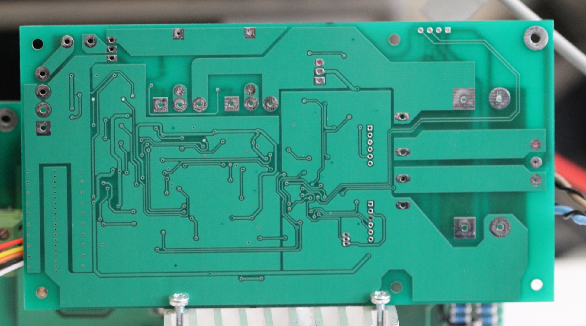
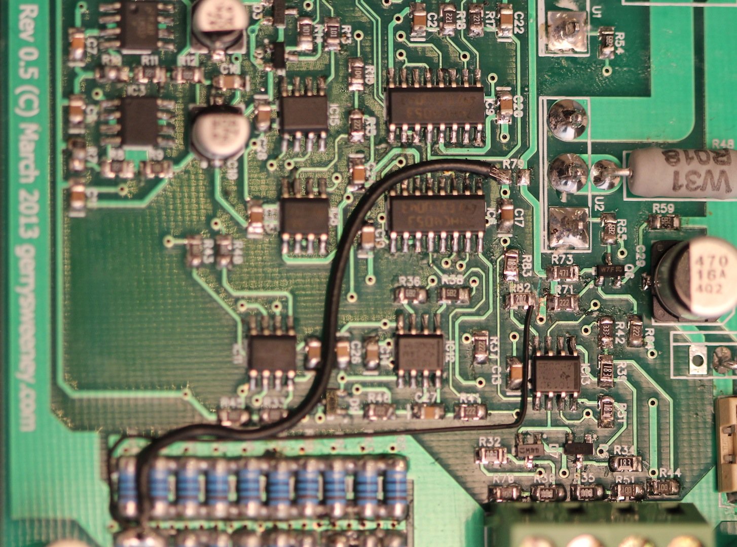
The BODGE WIRES
In laying out the PCB I forgot to pay attention to the star earthing I had set out in the previous post. The impedance of the ground path makes a big difference when you are looking at the lower 1mV of the range. Using DipTrace I had to use a ZERO ohm resistor to properly segregate GND and GNDANALOG nets, but I physically routed to the GND side of that resistor to the wrong point. I done a pretty similar thing on the low-side current sense connection. As a result there are two bodge wires on the board (see photo below). The first is the GNDANALOG to GND connection – Instead of installing R79 (which is ZERO ohm) I have taken a wire from the bottom pad down to the low-side of the current sense resistor array. The second is slightly more difficult to do, I had to cut the track from the top pad of R82 and then again take a wire down to the low-side of the current shunt resistor.
Thermal Management
In order to manage the thermal properties of the module, the firmware simply uses the temperature measurement of the heat sink to set the fan speed calculated on the following basis: –
below 25 degrees centigrade – FAN is idle at its lowest speed (0% PWM)
25 to 50 degrees centigrade – FAN is driven with variable PWM 25 degrees = 1%, 50 degrees = 100%, which is a rate of 4% per degree of temperature rise
more than 50 degrees centigrade – FAN is driven at 100%
Controlling a 4-wire fan is pretty easy, the specification developed by Intel describes the electrical interface and requirements for both fan control as well as fan manufacturers. I have added the Intel 4-Wire PWM Controlled Fan Spec as a download on this page for convenience. The fan I tested and used in the video above runs at about 1500 RPM to 3400 RPM with a 0-100% duty cycle on the PWM control signal. The taco output is open collector and provides 2 pulses per revolution.
Next time I am going to *try to* characterize the PSU. I don’t have much experience doing this which is why I say I am going to *try* – none the less I should be able to pull together some basic specs and test conditions.
Following that, I am going to design and make a front panel controller for the PSU. Although I am making this specifically for this project I am thinking about making this more generic so it can be used in other systems and/or test equipment. The basic goal is to create a single PCB front panel with a 4×20 VFD display, some buttons and controls, a micro controller (PIC32 or maybe ARM) with RS232, USB, Ethernet (and possibly a GPIB interface module) with 3-4 independent TTL level internal serial interface channels (to connect to PSU modules for example). Don’t know, all just thoughts at the moment, we shall see…